

Primary Lithium Battery Testing: What OEM Engineers Should Verify Before Mass Production
A primary lithium battery can pass a supplier datasheet check and still fail inside the finished product. The difference is system validation: confirming that the exact production-intent cell or pack, connector, power path, firmware, enclosure, and operating profile work together at the worst credible conditions.
This article provides a release-oriented test framework rather than another explanation of one battery characteristic. For focused technical background, PKCELL already publishes separate guides on why open-circuit voltage is not enough, Li-SOCl2 passivation, and field-failure troubleshooting. Here, the goal is to turn those risks into a controlled pre-production validation plan.
Start by Separating Verification, Qualification, and Release
These terms answer different questions:
- Design verification: does the battery solution meet the written electrical, mechanical, environmental, and interface requirements?
- Device qualification: does the production-intent battery work in the complete device across the intended use conditions?
- Production release: can the approved design be built, inspected, tested, documented, and traced consistently?
A compliance or transport test is not automatically device validation. Likewise, one successful bench sample does not demonstrate production repeatability. The OEM’s release decision should combine evidence from the battery supplier, internal engineering tests, the finished device, and the pilot build.
The right question is not “Did the battery pass?” It is “Did the correct battery configuration pass the correct test, in the production-intent device, at the defined worst case?”
Build a DVP&R Before You Start Testing
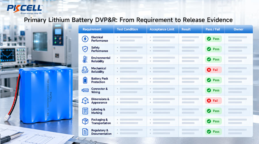
A Design Verification Plan and Report, commonly called a DVP&R, connects every requirement to a test method and a result. It prevents a familiar problem: collecting attractive graphs without proving the condition that actually controls field reliability.
For each test, record:
- Requirement or risk being verified
- Exact cell or pack part number and drawing revision
- Battery lot, production date, assembly date, and storage history
- Device hardware, firmware, radio settings, and load configuration
- Sample quantity and selection method
- Preconditioning, rest time, state of life, and temperature
- Equipment, measurement location, sampling rate, and test sequence
- Numeric pass/fail criteria defined before testing
- Raw data location, anomalies, deviations, and final disposition
Do not copy datasheet values into the pass column without checking their test conditions. PKCELL’s guide to reading a Li-SOCl2 battery datasheet explains why capacity, pulse current, cutoff voltage, and temperature must be interpreted together.
Test the Corners, Not Only the Nominal Condition
A useful test matrix varies more than temperature. Battery history, state of life, load severity, network behavior, and assembly configuration can interact. The matrix should cover combinations that create the least voltage margin or highest reliability risk.
| Test dimension | Examples to include | Why it matters |
|---|---|---|
| Battery state | Fresh, after planned storage, after extended low-current standby, simulated late-life condition | Performance can change with history and remaining voltage margin |
| Temperature | Room condition, minimum operating temperature, relevant high-temperature exposure | Temperature affects impedance, usable energy, components, and mechanical fit |
| Device load | Startup, sensing, radio attach, transmit, retries, alarm, motor or valve event | The highest current is not always the longest or most difficult event |
| Signal condition | Strong network, weak network, delayed attach, repeated retries | Real communication energy may exceed a scripted pulse |
| Assembly | Production wires, connector, welds, protection parts, enclosure, regulator, and firmware | Interconnect losses are invisible in a bare-cell test |
| Build stage | Engineering sample, verification build, pilot lot, first production lot | Evidence must move from concept performance to process repeatability |
For Li-SOCl2 designs, first activation after storage deserves its own condition. PKCELL’s article on shelf life versus service life explains why stored energy and immediate pulse readiness are separate qualification questions.
1. Confirm Identity, Revision, and Sample History
Testing the wrong revision produces confident but unusable evidence. Before electrical work begins, verify the manufacturer, chemistry, model, lot code, date code, pack drawing, connector, pinout, polarity, wire length and gauge, label, protection components, and packaging status.
Photograph the samples and record their history. If units were conditioned, depassivated, thermally exposed, partially discharged, or used in an earlier test, do not treat them as untouched samples. Separate destructive-test units from samples intended for later performance comparisons.
2. Verify Static Electrical and Interface Basics
Static checks are necessary screens, but they are not the final proof of performance. Depending on the product and agreed specification, incoming checks may include appearance, dimensions, weight, polarity, connector pinout, insulation, open-circuit voltage, and continuity.
For a custom pack, inspect details that can damage the device or create assembly variation:
- Maximum dimensions and critical tolerances
- Wire exit direction, length, gauge, color, and routing
- Connector manufacturer, part number, keying, and retention
- Pin assignment and polarity at the mating interface
- Insulation coverage, exposed conductor, strain relief, and label legibility
- Pack orientation, mounting, clearance, and assembly force
PKCELL’s customized battery service shows common lead, connector, termination, pack, and CAD design options. The approved drawing should define the exact configuration tested for the OEM project.
3. Measure Dynamic Voltage Where the Device Sees It
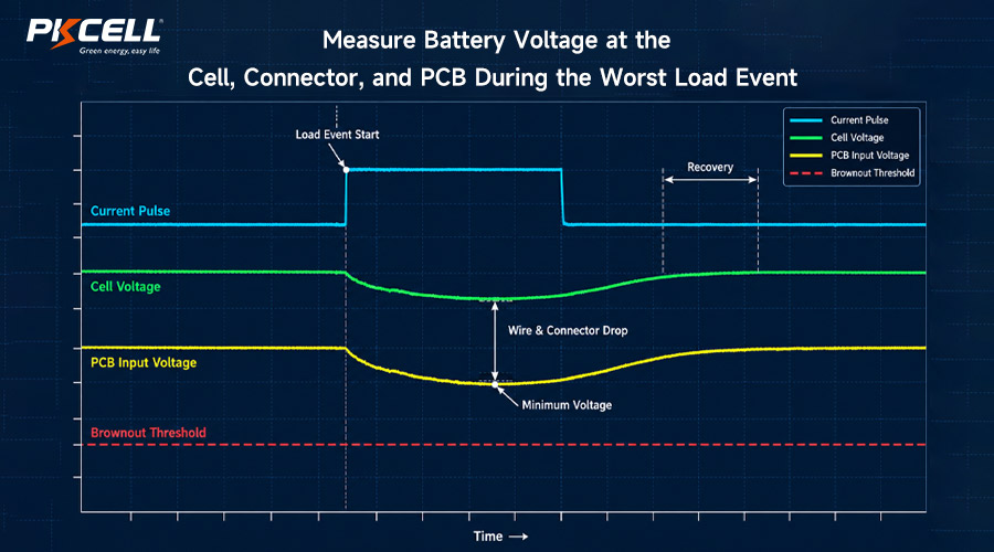
Open-circuit voltage measures a battery at almost no load. A production decision requires dynamic data. Capture current and voltage during the complete real event: boot, sensor warm-up, GNSS acquisition, network attach, transmission, alarm, flash, motor movement, or valve actuation.
Measure voltage at more than one point when possible:
- At the cell or pack terminals
- At the connector output
- At the PCB power input
- At a critical regulated rail when system behavior requires it
The difference between these traces reveals losses in tabs, welds, wires, connectors, holders, fuses, protection components, and PCB paths. Record minimum voltage, pulse duration, recovery behavior, reset or retry events, and their relationship to every relevant device threshold.
For wireless equipment, a programmable pulse may be useful for repeatability, but it should not replace a real modem or radio test. Weak signal, network attach, retransmission, firmware timing, and capacitor recharge can create a waveform that a simple rectangular pulse misses.
4. Verify Usable Energy and the Life Model
Nominal capacity is measured under stated laboratory conditions. The OEM needs usable energy above the device’s practical cutoff across the intended load and environment. Begin with measured current for every operating mode rather than component estimates alone.
Build the energy model from sleep, sensing, processing, memory, communication, retries, actuators, indicators, self-test, and abnormal events. Then include realistic allowances for storage, self-discharge, temperature, pulse losses, regulator efficiency, component tolerance, aging, and design margin.
A long-duration discharge test may not fit the program schedule. Accelerated or higher-load testing can support comparisons, but it should not be treated as a guaranteed field-life equivalent unless the acceleration model is technically justified. Clearly separate measured results, calculations, supplier data, and assumptions.
5. Validate Storage, Temperature, and Environmental Conditions
Environmental testing should reproduce the conditions that influence the battery and complete assembly. Depending on the application, the plan may address:
- Cold start and pulse performance at the minimum expected battery temperature
- Operation after the maximum planned warehouse or finished-goods storage period
- High-temperature storage followed by activation at a lower temperature
- Temperature cycling and stabilization before measurement
- Vibration and shock with the production mounting method
- Humidity, condensation, salt, chemicals, or other identified exposure
- Post-environment inspection for leakage, deformation, insulation damage, loose connections, and electrical change
Do not test temperature without defining where it is measured and how long the complete assembly is allowed to stabilize. Chamber air temperature is not automatically the cell temperature. Preserve the test sequence because environmental exposure before an electrical test can reveal effects that separate tests miss.
6. Test the Mechanical Pack as a Manufactured Assembly
Pack reliability depends on construction as well as cell chemistry. Production-intent units should use the planned cells, tabs, welds, insulation, adhesive, shrink wrap or housing, wires, connector, label, and protection parts.
Verify fit in the actual enclosure and assembly process. Look for trapped wires, sharp edges, compressed insulation, excessive insertion force, insufficient service loop, strain transferred to welds, or a connector that can be mated incorrectly. Where product risk justifies it, define measurable retention, pull, vibration, or workmanship criteria.
Teams evaluating configurations can review PKCELL’s range of primary lithium battery packs. A catalog example is only a starting point; production release should reference the project-specific controlled drawing.
7. Confirm Safety Controls and Documentation Scope
Primary lithium batteries must not be recharged. The OEM should verify that the complete device cannot unintentionally apply charging or reverse current during normal operation, external power connection, fault handling, programming, servicing, or storage. Protection strategy, isolation, fusing, parallel-cell design, and misuse analysis should be reviewed with the battery supplier for the exact configuration.
Documentation must match the purchased item. Depending on chemistry, configuration, destination, device category, and shipping method, a project may need applicable transport, safety, material, or market documents. Do not assume a report for one cell automatically covers a modified multi-cell pack.
PKCELL publishes a battery certificate overview. Before release, request current documents and verify the manufacturer, production location, model designation, configuration, report status, revision, and destination scope.
8. Prove Device and Firmware Behavior
Battery validation is also firmware validation. A technically suitable battery may appear inadequate if firmware keeps a peripheral awake, repeats failed transmissions without a limit, starts multiple loads simultaneously, or uses a brownout threshold that leaves insufficient margin.
Use production-intent firmware to verify:
- Sleep current over enough time to catch scheduled wake events
- Startup sequence and inrush behavior
- Radio attach, transmit, receive, timeout, and retry logic
- GNSS cold start or sensor warm-up where applicable
- Actuator, valve, motor, alarm, or flash events
- Brownout detection, reset recovery, and data integrity
- Low-battery indication and shutdown behavior
- Fault cases that can create continuous or repeated current draw
If testing reveals resets or transmission failures, use PKCELL’s Li-SOCl2 troubleshooting workflow to separate passivation, low temperature, pulse overload, interconnect resistance, depletion, and downstream power issues.
9. Move from Engineering Samples to Pilot-Lot Evidence
Engineering samples show that a design can work. A pilot build shows whether the intended materials, tools, instructions, operators, inspection points, and tests can reproduce it.
| Pilot-build evidence | What the OEM should verify |
|---|---|
| Material identity | Approved cell, connector, wire, insulation, label, protection parts, and packaging |
| Process control | Assembly instructions, connection method, fixtures, polarity controls, and operator checks |
| Inspection results | Dimensions, appearance, electrical checks, workmanship, and agreed performance sampling |
| Traceability | Link between incoming cell lots, pack assembly lot, inspection records, and shipped product |
| Yield and deviations | Failure modes, rework, concessions, root causes, and corrective actions |
| Packaging and shipment | Pack protection, labels, carton identification, documents, and destination requirements |
Sample size should be based on risk, expected variation, test destructiveness, development stage, and customer or regulatory requirements. There is no responsible universal sample count for every battery project. Document why the selected quantity is sufficient for the decision being made.
Define Failure Handling Before a Sample Fails
A failed test should trigger evidence collection, not an immediate change of battery. Preserve the unit, waveform, fixture, environmental condition, firmware log, and configuration. Repeat only after deciding whether the repetition is checking reproducibility or changing the test.
A useful failure record includes the observed symptom, exact point of failure, battery and device identity, load trace, voltage trace, temperature, sequence, prior sample history, inspection findings, suspected causes, containment, root-cause evidence, corrective action, and retest plan.
Any change to the cell, pack design, connector, wire, protection component, firmware power behavior, regulator, enclosure, manufacturing process, or test method should be assessed for revalidation. Production approval applies to a controlled configuration, not merely a product name.
Mass-Production Release Checklist
- The exact battery or pack specification and drawing revision are approved.
- Electrical tests include the real device load and relevant voltage thresholds.
- Worst-case temperature, storage, signal, and state-of-life conditions are addressed.
- Mechanical fit, connector, polarity, insulation, and production assembly are verified.
- Firmware current behavior and failure recovery are validated.
- The life model uses measured duty-cycle data and documented assumptions.
- Required safety, transport, and market documents match the actual configuration.
- Pilot-lot inspection, traceability, yield, packaging, and deviations are reviewed.
- Open failures have documented disposition and completed retest evidence.
- Incoming inspection, retained samples, change notification, and production test requirements are defined.
Review Your Test Plan with a Battery Engineer
Send PKCELL your device waveform, voltage thresholds, operating environment, storage profile, pack drawing, firmware test modes, validation matrix, sample quantity, and production forecast for a project-specific recommendation and quotation.
Request an Engineering Review
Explore Primary Battery Solutions
Frequently Asked Questions
Is open-circuit voltage enough for incoming inspection?
No. OCV is a useful identity and screening check, but it does not prove pulse capability, loaded voltage, usable capacity, storage response, or performance above the device cutoff.
Should OEMs test the bare cell or the finished device?
Both serve different purposes. Controlled cell tests help compare battery behavior, while finished-device tests reveal wiring, connector, regulator, firmware, radio, actuator, and enclosure interactions.
How should end-of-life performance be tested?
Define expected late-life voltage and impedance conditions with the supplier, then verify the real device load and thresholds. A reduced laboratory supply voltage may not reproduce all battery behavior.
Does a UN38.3 test prove the battery will work in my product?
No. UN38.3 relates to lithium battery transport testing. It does not replace application-specific electrical, environmental, mechanical, firmware, service-life, or production validation.
How many battery samples should an OEM test?
The quantity should reflect project risk, expected variation, build stage, test type, destructiveness, confidence required, and applicable customer or regulatory rules.
When should an ER + HPC solution be evaluated?
It is worth evaluating when a device needs long standby energy plus demanding radio, GNSS, alarm, motor, or valve pulses. Review PKCELL’s ER + hybrid pulse capacitor options, then validate the selected configuration with the real waveform.
Conclusion
Primary lithium battery testing before mass production is a system-release exercise. The OEM must verify the exact product revision, dynamic voltage at the device, usable energy, environmental boundaries, mechanical assembly, firmware behavior, documentation scope, and pilot-lot repeatability. Tests become decision-ready only when conditions and acceptance limits are defined in advance and every result is traceable.
Use PKCELL’s custom battery pack RFQ checklist to organize project inputs, then contact PKCELL to discuss samples, pack configuration, technical documents, and production planning.
Post time: Sep-30-2026


