

Quick answer: if the open-circuit voltage looks normal but the device fails during boot, radio transmission, GNSS acquisition or valve operation, measure the voltage at the PCB power input during the complete event. The battery may still contain energy, but the loaded voltage can briefly fall below the device’s cut-off or brownout threshold.
- 1Reproduce the failure
- 2Capture the voltage dip
- 3Locate the resistance
- 4Identify the cause
- 5Validate the correction
Lithium thionyl chloride batteries are widely used in smart meters, trackers, alarms and industrial sensors because they combine high energy density, low self-discharge and long standby life. However, long-term energy storage and short-duration power delivery are different design requirements.
A device may sleep at a few microamps for hours and then demand a much higher current during network attachment or transmission. When that pulse causes the supply to cross the device’s minimum operating voltage, the result may be a reset, incomplete upload, repeated network registration or an apparently dead unit.
This article concentrates on the complete diagnostic process. For a deeper explanation of one specific mechanism, see PKCELL’s Li-SOCl2 battery passivation guide. Engineers evaluating available formats can also review the PKCELL 3.6V Li-SOCl2 battery range.
Why Normal Battery Voltage Does Not Rule Out a Brownout
A multimeter usually reports open-circuit voltage or a slowly changing average. It may not capture a millisecond-scale voltage collapse. By the time the failed device is inspected, the load has disappeared and the cell voltage may have recovered.
The cell’s dynamic impedance also contributes to the voltage drop. It varies with temperature, storage history, passivation, state of charge, pulse duration and current amplitude. Consequently, a stable open-circuit reading does not prove that the complete battery system can keep the device operating during its highest load.
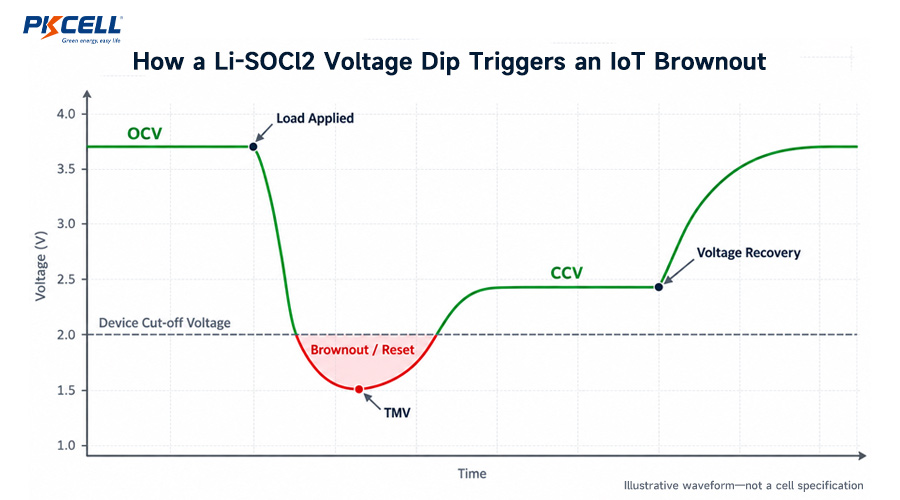
The decisive measurement is not the resting battery voltage. It is the lowest voltage reaching the device during the worst real operating event.
Start With the Field Symptom
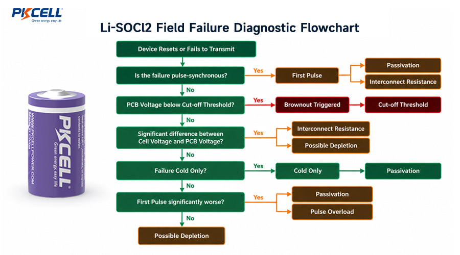
| Field symptom | Likely causes | First measurement | Useful diagnostic clue |
|---|---|---|---|
| Device resets when transmission starts | Excessive pulse demand, high source impedance, insufficient pulse support or high cut-off voltage | Minimum PCB input voltage during the entire transmission | The reset occurs when voltage crosses the brownout threshold |
| First startup after storage fails, but a later attempt works | Passivation-related voltage delay | First-pulse waveform after representative storage | The initial voltage dip improves during later controlled events |
| Failure occurs only in cold weather | Higher cell impedance, capacitor ESR or insufficient regulator margin | Loaded voltage at the minimum cell temperature | The same device works at room temperature |
| Cell voltage remains acceptable but PCB voltage collapses | Connector, holder, weld, wire, protection device or corrosion resistance | Simultaneous voltage at the cell terminals and PCB input | A measurable voltage difference appears across the power path |
| Uploads fail mainly in weak network coverage | Long network attach, repeated transmissions or incomplete pulse-capacitor recharge | Current and voltage during a real weak-signal cycle | Failure follows retries rather than one normal transmission |
| Loaded voltage stays low and recovery is poor | Depletion, aging, damage or unsuitable cell selection | Model-specific load test and operating history | The problem remains after temperature and connection effects are excluded |
Five-Step Li-SOCl2 Battery Troubleshooting Process
Reproduce the Exact Event That Fails
Test the actual operating sequence rather than a simplified average load. Wireless devices may have separate startup, network attach, transmit, receive and retry peaks. A valve or motor may require much more current when starting than while moving.
- Record the operating mode and firmware version.
- Log ambient temperature and actual cell temperature.
- Record network signal strength, attach time and retry count.
- Note storage duration and storage temperature.
- Identify whether the first event, every event or only repeated events fail.
- Read MCU reset flags or power-management logs where available.
Decision: If the supply stays above the validated operating threshold, investigate firmware, watchdog, RF interference and other hardware faults. If the reset matches a voltage dip, continue with the battery and power-path investigation.
Capture OCV, TMV, CCV and PCB Minimum Voltage
Use an oscilloscope or data-acquisition system fast enough to capture the shortest load event. Measure close to the device power input because a slow multimeter can miss the voltage minimum completely.
- Open-circuit voltage: cell voltage before the load is applied.
- Transient minimum voltage: the lowest voltage immediately after the load begins.
- Closed-circuit voltage: voltage after the initial transient while the load remains active.
- Recovery voltage: the voltage response after the load ends.
- PCB minimum voltage: the lowest voltage received by the regulator, modem or MCU.
- Current waveform: peak current, duration, frequency and rest interval.
Use short probe connections and capture current and voltage on the same time base. This shows whether the device reset is aligned with the beginning of the pulse, the end of a long transmission or a sequence of retries.
Locate Where the Voltage Is Being Lost
Measure at both the cell terminals and the PCB input during the same event. The difference between those traces reveals losses in battery tabs, welds, wires, holders, connectors, fuses, protection components and PCB traces.
- If both voltages collapse together, investigate cell impedance, passivation, temperature, depletion and pulse capability.
- If cell voltage remains acceptable but PCB voltage collapses, inspect the interconnect and protection path.
- If the regulator input is stable but a downstream rail fails, check regulator dropout, transient response, capacitance and layout.
Even modest contact resistance can become important during a high-current pulse. Where pack construction contributes to the failure, PKCELL can provide custom primary lithium battery packs with application-specific leads, connectors, tabs and housings.
Separate the Main Root Causes
Passivation-related voltage delay
Passivation is a normal characteristic of Li-SOCl2 chemistry. A protective layer forms on the lithium surface and contributes to low self-discharge. After storage or extended low-current standby, however, it may increase initial impedance and cause voltage delay.
Suspect passivation when the first loaded pulse is the worst and later controlled events improve. Compare cells with the same storage and temperature history. Any conditioning or depassivation process must follow the supplier’s instructions for the exact model.
Low-temperature impedance
Cold conditions generally increase internal resistance and produce a larger voltage drop for the same load. The cell may still contain substantial energy, but the device cannot access it above its minimum operating voltage.
Stabilize the entire unit at the required minimum temperature before testing. Placing a cold enclosure around a warm battery does not reproduce field conditions. For deeper temperature analysis, read how temperature affects Li-SOCl2 capacity and pulse current.
Pulse demand beyond the selected cell
Capacity and pulse capability are separate selection criteria. A larger energy-type cell can provide more capacity and some additional current headroom, but it may still be unsuitable for a demanding cellular, motor or valve pulse.
Compare the real current waveform with the exact cell datasheet and its stated test conditions. The ER14505, ER26500 and ER34615 comparison explains why cells should be selected by power profile rather than amp-hours alone. Applications requiring stronger direct current delivery can also evaluate an ER power-type spiral battery.
Undersized or incompletely charged pulse support
For devices combining long standby periods with high-current events, an ER cell can supply long-term energy while a hybrid pulse capacitor supports short pulses. Correct selection must account for capacitance, ESR, leakage, temperature, pulse duration and recharge time.
- Measure capacitor voltage immediately before transmission.
- Capture the instantaneous ESR-related drop.
- Measure voltage droop across the complete event.
- Check recharge time after transmission.
- Repeat the test with realistic network retries.
- Validate at low temperature and near end of life.
PKCELL’s HPC sizing guide for NB-IoT applications explains the first-pass relationship between pulse current, duration and permitted voltage droop. Engineers can then compare suitable ER + HPC IoT battery pack solutions.
Actual depletion, aging or unexpected energy consumption
If loaded voltage remains low after connection, temperature and passivation effects have been considered, examine the unit’s energy history. Unexpected sleep current, excessive network retries, elevated-temperature exposure or a peripheral that never powers down can shorten service life.
Update the energy model using measured operating modes rather than nominal capacity alone. The LoRaWAN and NB-IoT battery-life calculation guide provides a cycle-based approach that includes sleep, active and communication events.
Correct the Cause and Repeat Worst-Case Validation
| Confirmed cause | Engineering directions to evaluate | Required validation |
|---|---|---|
| Passivation-related first-pulse delay | Supplier-approved conditioning, staged startup, power-type cell or ER + HPC architecture | First activation after the maximum planned storage period |
| Cold-temperature voltage sag | Greater pulse margin, lower-ESR architecture, adjusted load sequence or suitable cell selection | Complete device stabilized at minimum temperature |
| Pulse exceeds cell capability | Power-type cell, correctly sized HPC, staged loads or revised communication profile | Worst pulse duration, retries and end-of-life impedance |
| Interconnect resistance | Improved weld or crimp, shorter wire, suitable connector and corrosion control | Voltage drop across every power-path segment |
| Cut-off or regulator margin | Review brownout settings, converter dropout and transient response within component limits | All modes, temperatures and component tolerances |
| Unexpected consumption | Reduce sleep leakage, limit retries, revise firmware timing or increase validated capacity | Long-duration current logging and an updated energy budget |
Do not approve a correction after testing only a fresh battery at room temperature. Repeat the real device sequence after representative storage, at minimum temperature, under weak network coverage and with suitable end-of-life margin.
Safety warning: Li-SOCl2 cells are primary lithium batteries. Do not recharge, short-circuit, crush, puncture, disassemble or heat them. Do not attempt uncontrolled depassivation. Use only a model-specific procedure approved by the battery manufacturer, and replace damaged, leaking, swollen or overheated cells according to the applicable handling instructions.
Recommended Bench Test Matrix
- Fresh production cell at room temperature
- Cell after representative warehouse storage
- Cell after extended low-current standby
- Minimum specified cell temperature
- Beginning-of-life condition
- Simulated end-of-life condition
- Strong network signal
- Weak signal with realistic retries
- Minimum pulse interval
- Maximum expected pulse duration
- Cell-terminal voltage measurement
- PCB-input voltage measurement
- Production wires and connectors
- Production firmware and RF settings
Define the pass criteria before testing. These may include minimum permitted voltage, successful transmission rate, maximum network attach duration, recovery time, reset count and temperature stabilization requirements.
Common Diagnostic Mistakes
- Checking only open-circuit voltage: the critical failure happens under load.
- Testing only fresh cells: deployed cells face storage, aging and temperature cycling.
- Selecting by average current: average current estimates energy use, while peak current determines voltage stability.
- Ignoring board-level voltage: cell voltage alone cannot reveal connector or wire losses.
- Calling every first-pulse dip passivation: cold, depletion and resistance can produce similar symptoms.
- Ignoring network retries: weak coverage may extend active time and repeat high-current pulses.
- Adding capacitance without checking ESR: capacitance value alone does not define transient performance.
- Lowering the brownout setting without validation: other components may then operate outside their approved range.
What to Send PKCELL for an Engineering Review
Providing measured application data helps the battery supplier investigate the failure faster. Include as much of the following information as possible:
- Device type and use environment
- Existing battery or cell part number
- Sleep, active and peak current
- Pulse duration, frequency and retry pattern
- Device cut-off or brownout voltage
- Measured OCV, TMV, CCV and PCB minimum voltage
- Operating and storage temperature range
- Storage duration before activation
- Wireless technology and typical signal conditions
- Target service life and available battery space
- Connector, wire, tab and certification requirements
- Oscilloscope waveforms and failed-unit history
Request a Li-SOCl2 Failure Review
Send PKCELL your load waveform, minimum voltage, temperature range and storage conditions. The engineering team can help compare an ER energy cell, ER power-type cell, ER + HPC system or customized primary battery pack for your device.
Frequently Asked Questions
Why does a Li-SOCl2 battery show 3.6V while the device still resets?
The 3.6V reading may be an open-circuit value. Cell impedance and resistance in the power path can pull the PCB voltage below its brownout threshold during startup or transmission. Measure the minimum voltage during the complete event.
Does a lithium battery voltage drop mean the cell is empty?
Not necessarily. Passivation, cold temperature, a demanding pulse, interconnect resistance or a high cut-off voltage can make stored energy temporarily inaccessible. Loaded testing is required to distinguish these conditions from depletion.
Why does an IoT device fail only on its first transmission?
A poor first event after storage can indicate passivation-related voltage delay. Cold-start demand, capacitor charge state and startup sequencing should also be evaluated before confirming the cause.
Why are battery brownouts more common at low temperature?
Cold conditions generally increase battery impedance. The same transmission current then produces a larger voltage drop and may cross the device’s cut-off threshold.
Will a larger Li-SOCl2 cell always prevent transmission failures?
No. A larger energy-type cell provides more capacity and may provide additional current headroom, but the architecture must still match the pulse amplitude, duration, temperature and device cut-off voltage. A power-type cell or ER + HPC solution may be more suitable.
Can a Li-SOCl2 battery be depassivated by briefly shorting it?
No. Never short-circuit a Li-SOCl2 battery. Conditioning must use a controlled, model-specific procedure supplied or approved by the battery manufacturer.
Conclusion
Reliable Li-SOCl2 battery troubleshooting begins with the actual event that fails. Capture the current waveform and minimum PCB voltage, compare cell-terminal voltage with board-input voltage, and then isolate passivation, temperature, pulse demand, resistance, cut-off behavior and depletion through controlled tests.
The goal is not simply to install a battery with more amp-hours. It is to design a power system that keeps the device above its required voltage after storage, in cold conditions, during communication retries and near the end of its service life. To discuss a field failure, send PKCELL your device load profile and request a battery recommendation.


