

CR2032 With Tabs vs Holder: Best Choice for OEM PCBs
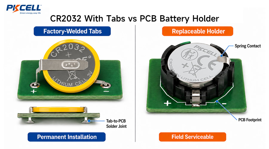
OEM engineers integrating a CR2032 battery into a printed circuit board typically choose between two approaches: a cell with factory-welded solder tabs or a replaceable CR2032 installed in a PCB battery holder.
Both options can provide reliable 3V backup power, but they lead to different assembly processes, mechanical risks and maintenance strategies. The better choice depends on whether the battery should be permanent or replaceable, how much PCB space is available, and what the product will experience in the field.
OEM teams can compare the
standard PKCELL CR2032 battery
with available
lithium coin cells with tabs and leads
before finalizing the PCB architecture.
CR2032 With Tabs vs Battery Holder
| Design Factor | CR2032 With Tabs | CR2032 Battery Holder |
|---|---|---|
| Battery replacement | Usually requires desoldering or module replacement | Cell can normally be replaced without PCB soldering |
| Electrical connection | Factory-welded tabs soldered to the PCB | Spring contacts press against the cell terminals |
| Contact interfaces | Weld and solder joints | Solder joints plus removable mechanical contacts |
| Vibration resistance | Potentially strong when the cell and tabs are properly supported | Depends on holder retention and contact design |
| PCB footprint | Can be compact with custom horizontal or vertical tabs | Usually requires the holder outline, contacts and insertion clearance |
| Product height | Depends on tab orientation and cell position | Depends on horizontal, vertical, low-profile or insulated holder design |
| Assembly | Battery is introduced into the soldering process | Holder can be assembled first and the cell inserted later |
| Heat exposure | Battery-body temperature must be controlled during tab soldering | Cell can remain outside the reflow process when inserted after soldering |
| Field maintenance | Less convenient | Better for scheduled battery replacement |
| Polarity error risk | Reduced after correct factory assembly and PCB installation | Possible during field replacement unless clearly marked or keyed |
| Best fit | Sealed, fixed-life and vibration-prone assemblies | Serviceable equipment with an accessible battery compartment |
The mounting method does not increase CR2032 capacity. A tabbed battery and a loose cell provide the capacity of the underlying cell model; tabs or holders only change how that energy source is integrated.
CR2032 With Solder Tabs
A tabbed CR2032 uses metal tabs, pins or leads that are welded to the cell by the battery manufacturer. The tabs, rather than the battery case, are then soldered to the PCB or connected to the product wiring.
Common configurations include:
- Horizontal tabs extending in the same direction
- Opposing horizontal tabs
- Vertical PCB pins
- Axial or radial lead configurations
- Lead wires with insulation or a connector
Advantages of a Tabbed CR2032
- Secure electrical connection: Welded and soldered joints avoid a removable contact interface.
- Better retention: A correctly supported cell is less likely to move or disconnect under vibration.
- Controlled polarity: Factory-configured tabs reduce the chance of end-user insertion errors.
- Flexible orientation: Horizontal or vertical designs can optimize board area or enclosure height.
- Suitable for sealed products: No external battery door is required.
- Reduced service access: Useful when the product is intended to operate without field maintenance.
Limitations of a Tabbed CR2032
- The battery is not easily replaceable by the user.
- Battery installation exposes the assembly to additional thermal-process constraints.
- Tab spacing, orientation and polarity must match the PCB footprint exactly.
- Changing battery suppliers may require mechanical requalification.
- Replacing a depleted battery can require PCB rework.
- The finished assembly may require extra insulation or mechanical support.
PKCELL’s
CR2032 tabbed product page
shows available integration formats. Confirm the underlying cell capacity, terminal drawing and approved specification directly with the supplier before production.
CR2032 PCB Battery Holders
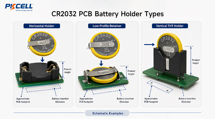
A battery holder creates a removable mechanical and electrical interface between the CR2032 and PCB. Holder designs include horizontal top-entry sockets, low-profile retainers and vertical through-hole formats.
Advantages of a CR2032 Holder
- Easy replacement: The battery can be changed without desoldering the PCB.
- Longer product life: A depleted cell does not automatically make the entire assembly obsolete.
- Battery added after soldering: The cell can be kept away from reflow or wave-solder heat.
- Standard supply options: Many PCB holders offer published drawings, CAD files and qualification reports.
- Flexible service model: Users, technicians or service centers can perform scheduled replacement.
Limitations of a CR2032 Holder
- The holder adds component cost and PCB area.
- Spring contacts introduce an additional resistance interface.
- Retention must be verified for shock, vibration and drop conditions.
- Contact surfaces may be affected by contamination, humidity or corrosion.
- The enclosure needs safe access and enough room to remove the battery.
- Incorrect polarity or the wrong coin-cell model may be inserted during service.
A holder should be selected from its complete component specification. For example, commercial holders may specify compatible battery models, contact plating, temperature range, mating cycles, vibration performance and a recommended PCB layout.
PCB Layout and Assembly Considerations
PCB Footprint and Mechanical Envelope
Do not create the footprint from the nominal 20mm battery diameter alone. Use the approved terminal or holder drawing and include:
- Pad or through-hole dimensions
- Tab or pin spacing and tolerances
- Battery and holder maximum outline
- Insertion and removal clearance
- Keep-out areas around conductive surfaces
- Enclosure and battery-door clearance
- Pick-and-place or assembly-tool access
Horizontal vs Vertical Mounting
A horizontal cell typically minimizes assembly height but consumes more board area. Vertical tabs or a vertical holder can reduce PCB footprint but increase product height and sensitivity to bending or vibration forces.
For vertical designs, evaluate the center of mass, pin stress, enclosure support and drop direction. The battery should not rely only on solder joints for mechanical support in a severe-vibration application.
Soldering and Reflow Planning
A surface-mount holder may be compatible with automated placement and reflow when the selected holder specification explicitly permits it. Install the CR2032 after the holder and PCB have cooled.
A tabbed battery should not pass through an unrestricted reflow profile. Panasonic’s guidance for coin-type lithium battery terminations emphasizes limiting heat transfer to the battery body and prohibits direct soldering to the cell. Follow the exact battery supplier’s approved soldering method, temperature, duration and cooling requirements.
Electrical Layout
Route the battery connection away from noisy or high-current paths when it powers RTC, memory or backup circuits. Consider reverse-polarity protection, leakage current through protection components and test-point access.
Account for the resistance of tabs, welds, holder contacts and PCB traces when the device has pulse loads. A battery holder that performs well in a microamp RTC circuit may still require additional validation in a wireless transmitter.
Reliability, Serviceability and Lifecycle Cost
The lowest component price does not always produce the lowest lifecycle cost. Evaluate assembly, testing, warranty, maintenance and replacement together.
| Lifecycle Question | Tabbed CR2032 Impact | Holder Impact |
|---|---|---|
| Will the battery outlast the product? | Strong candidate if validated | Replacement feature may be unnecessary |
| Is the product expected to receive a battery replacement? | Requires rework or module replacement | Supports planned replacement |
| Is the enclosure sealed? | Avoids a user-accessible battery door | Replacement may require breaking the seal |
| Will the device experience vibration? | Secure when tabs and cell are mechanically supported | Requires validated retention and contact force |
| Is automated SMT assembly required? | Battery may need a separate controlled process | Some holders support tape-and-reel and reflow assembly |
| Is field labor expensive? | May increase service or board-replacement cost | Can reduce replacement labor if safely accessible |
Which Option Fits Different OEM Applications?
| Application | Likely Starting Point | Reason |
|---|---|---|
| Motherboard RTC or CMOS backup | Battery holder | Battery replacement can extend the service life of the board. |
| Sealed smart sensor | Tabbed CR2032 | Secure permanent connection without an external battery door. |
| Industrial controller | Depends on service plan | Use a holder for scheduled maintenance or tabs for a fixed-life module. |
| Vibration-prone portable device | Tabbed CR2032 or qualified holder | Mechanical retention and contact continuity require testing. |
| Disposable medical accessory | Tabbed CR2032 | Controlled assembly and limited user access may be preferred. |
| Serviceable medical instrument | Qualified battery holder | Supports controlled battery replacement during maintenance. |
| Consumer remote or control panel | Battery holder | The user is expected to replace the cell. |
| Embedded memory module | Tabbed CR2032 | Compact integration and fixed polarity are useful. |
For additional CR2032 capacity, temperature and mounting considerations, see the
CR2032 specification and selection guide.
OEM Selection Checklist
- Define the product service model.
Decide whether users, technicians or nobody should replace the battery. - Set the mechanical limits.
Confirm PCB area, maximum height, enclosure clearance and insertion access. - Describe field conditions.
Document vibration, shock, humidity, contamination and temperature exposure. - Define the assembly process.
Determine whether SMT reflow, wave soldering, selective soldering or manual soldering will be used. - Select the exact termination.
Approve tab direction, spacing, polarity, material and dimensional tolerances. - Review the electrical load.
Include standby current, pulse current, cutoff voltage and permitted connection resistance. - Test service operations.
For holders, evaluate insertion, extraction, polarity errors and battery-door access. - Validate production samples.
Test the final cell, holder or tabs, PCB, enclosure and assembly process together.
PKCELL supports selected tab, pin, lead-wire, connector and insulated battery configurations through its
custom battery service.
Common Design Mistakes
- Soldering directly to a standard bare CR2032
- Creating a PCB footprint without the supplier’s approved drawing
- Assuming every CR2032 holder supports reflow soldering
- Ignoring battery insertion and removal clearance
- Using solder joints as the only mechanical support under vibration
- Failing to test holder contact resistance near battery end of life
- Allowing a serviceable battery to be installed with reversed polarity
- Specifying tabs without a clear orientation and polarity drawing
- Placing conductive PCB features under an uninsulated holder
- Assuming a tabbed cell has more capacity than the underlying CR2032
Frequently Asked Questions
Is a tabbed CR2032 better than a battery holder?
It is better for sealed, fixed-life or vibration-prone products. A holder is better when the battery must be replaced without PCB rework.
Can I solder wires directly to a CR2032?
No. Use a cell with factory-welded tabs or leads. Direct soldering can overheat the cell and damage its seal or internal structure.
Can a CR2032 battery holder go through reflow?
Only when the exact holder specification approves the planned reflow profile. The battery should normally be inserted after the soldering process and after the PCB has cooled.
Are horizontal or vertical CR2032 tabs better?
Horizontal tabs generally reduce assembly height, while vertical tabs can reduce PCB area. The right choice depends on enclosure geometry, mechanical support and assembly process.
Do solder tabs increase CR2032 capacity?
No. Capacity is determined by the underlying cell. Tabs, leads and holders only change the mechanical and electrical connection.
What should be included in a custom tab drawing?
Include cell model, tab material, width, thickness, length, spacing, bend geometry, polarity, orientation, insulation and PCB footprint.
Conclusion
A CR2032 with factory-welded tabs offers compact, secure integration for sealed or maintenance-free OEM products. A CR2032 battery holder adds serviceability and keeps the battery outside the PCB soldering process, but it introduces an additional contact interface and requires replacement access.
Select tabs when fixed polarity, vibration resistance and permanent installation are priorities. Select a holder when battery replacement is part of the product’s service strategy. In both cases, use approved drawings and validate the complete PCB, enclosure and manufacturing process.
Post time: Sep-01-2026


