

AUTOMOTIVE BATTERY ENGINEERING
Battery Requirements for TPMS Sensors: Temperature, RF Pulses, and Long Service Life
A direct tire pressure monitoring system (TPMS) relies on a compact power source inside each wheel-mounted sensor. The battery must support sensing and wireless communication while operating through temperature changes, vibration, and years of service. Selecting a suitable cell therefore requires more than comparing nominal capacity.
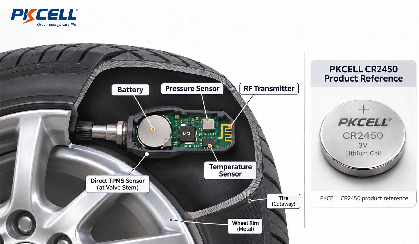
Key selection principleChoose a TPMS battery from the complete sensor load profile and qualification requirements: operating temperature, RF pulse current, service-life target, mechanical integration, and end-of-life voltage. A standard CR coin cell should not be assumed suitable for every wheel-mounted TPMS design.
- 01 Temperature capability
- 02 RF pulse performance
- 03 Service-life calculation
- 04 Mechanical integration
01
SYSTEM ARCHITECTURE
Which TPMS Designs Require an Internal Battery?
Battery selection begins by identifying the TPMS architecture. A direct TPMS measures pressure using electronic sensors installed in or on the wheels. Each battery-powered sensor typically contains a pressure sensor, temperature sensor, processing electronics, and an RF transmitter.
An indirect TPMS uses vehicle wheel-speed information, usually from the ABS system, to identify tire-pressure changes. It does not normally require a separate battery-powered pressure sensor inside each wheel.
DIRECT TPMS
Battery-powered wheel sensor
Requires an onboard power source for sensing, processing, and wireless data transmission.
INDIRECT TPMS
Vehicle-based monitoring
Uses existing wheel-speed signals and vehicle electronics rather than a dedicated battery inside each wheel.
This article focuses on direct TPMS sensors with integrated primary batteries.
02
THERMAL PERFORMANCE
Temperature Is a Critical Battery Requirement
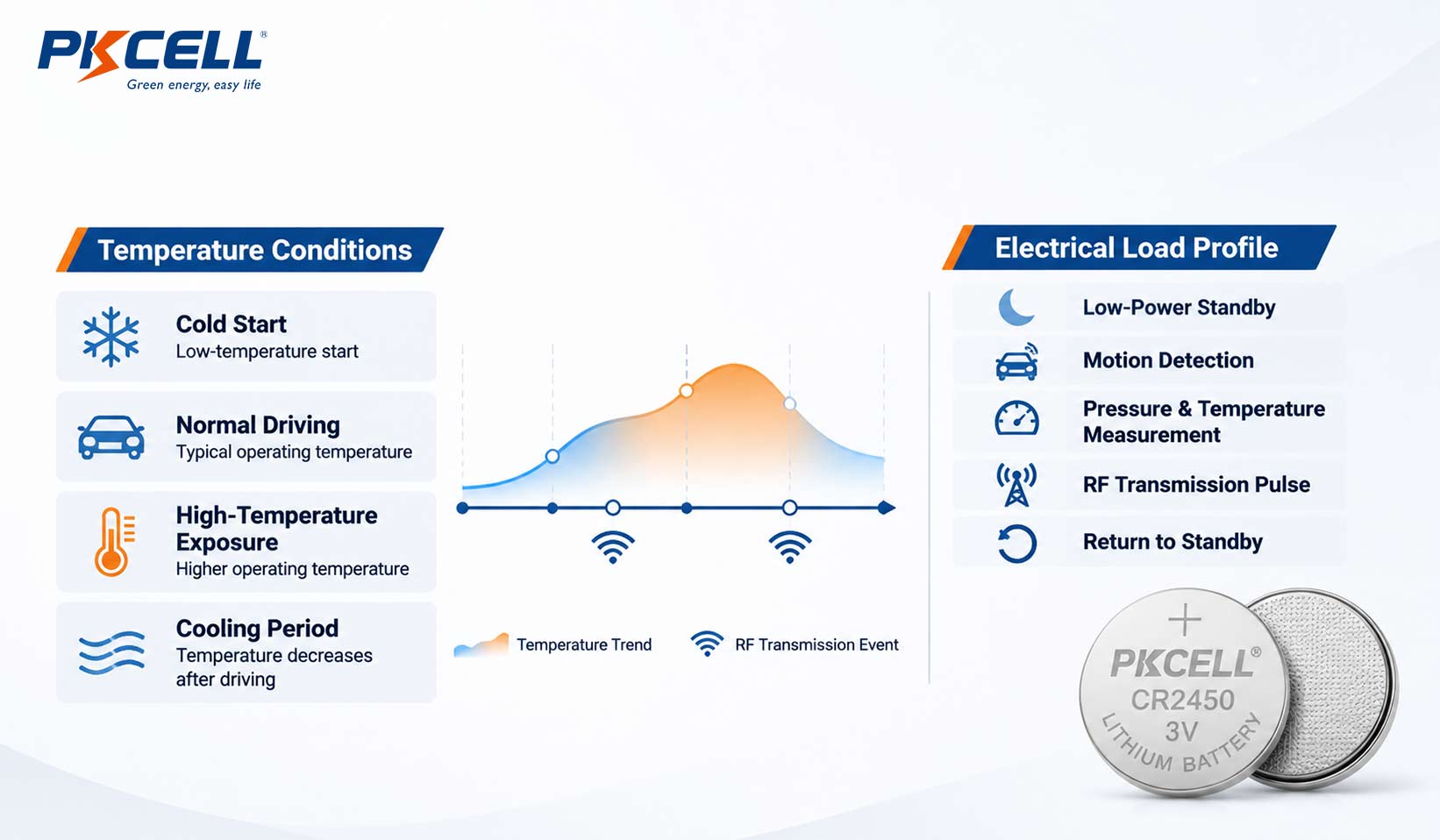
A wheel-mounted sensor experiences a different thermal environment from electronics inside the passenger compartment. Ambient conditions, road operation, heat transferred from braking components, tire behavior, and parking conditions can all affect the sensor’s temperature profile.
Temperature influences usable capacity, internal resistance, voltage response under load, and long-term aging. The battery must therefore be evaluated across the actual operating and storage conditions of the sensor assembly.
| Thermal condition | What engineers should verify |
|---|---|
| Cold start | Loaded voltage and RF transmission performance at the minimum specified temperature. |
| High-temperature operation | Cell operating limit, exposure duration, aging behavior, and enclosure temperature. |
| Temperature cycling | Performance after repeated heating and cooling cycles. |
| Storage before installation | Self-discharge and the effect of storage temperature and duration. |
| End-of-life condition | Required sensing and communication behavior near the defined replacement threshold. |
Do Not Treat Every CR Coin Cell as a High-Temperature TPMS Battery
Specialized high-temperature CR lithium coin cells are available for automotive applications, but their temperature ratings are model-specific. A standard CR2032 or CR2450 must not be assumed to meet the thermal requirements of a wheel-mounted sensor simply because it has the same nominal chemistry or voltage.
03
PULSE LOAD
RF Transmission Requires More Than a Capacity Check
A direct TPMS sensor spends much of its operating time in a low-power state. It periodically wakes to measure pressure and temperature, process the readings, and transmit data to the vehicle receiver. During RF transmission, current demand can rise above the standby level.
If the cell’s internal resistance is too high for the load, terminal voltage may fall during transmission. Depending on the sensor design, this can contribute to transmitter instability, resets, incomplete communication, or premature low-voltage warnings.
Measure the Actual Transmission Waveform
Battery evaluation should use the sensor’s real current profile rather than a single average-current figure. Record peak current, pulse duration, repetition interval, loaded voltage, and voltage recovery. Repeat the measurements at relevant temperature points and near the defined end-of-life condition.
04
SERVICE LIFE
Estimate Battery Life From the Complete Duty Cycle
TPMS battery service life depends on the energy consumed by standby operation, measurements, wireless transmissions, and other sensor functions. Transmission frequency and temperature can materially change the result.
PRELIMINARY CAPACITY ESTIMATEQ (mAh) = Isleep × tsleep + Σ(Ievent × tevent × N) / 3600Use current in mA, time in hours for standby, event duration in seconds, and the number of events N.
This is an initial charge-budget calculation, not a service-life guarantee. The final estimate must account for usable capacity at the actual load and temperature, self-discharge, aging, voltage cutoff, transmission retries, and an engineering reserve.
05
MECHANICAL INTEGRATION
Check Vibration, Rotation, and Battery Connections
A battery inside a wheel-mounted sensor is exposed to vibration, shock, and rotational acceleration. The cell, enclosure, PCB, and electrical connections must be designed as one assembly.
- Cell retention: Confirm that the battery remains securely supported in the sensor housing.
- Terminal integrity: Evaluate welded tabs, leads, and connection resistance after mechanical testing.
- Insulation: Prevent movement or deformation from creating an electrical short.
- Environmental sealing: Verify the complete assembly against the moisture and contamination conditions specified for the application.
For compact OEM assemblies, a factory-tabbed coin cell may simplify PCB or wiring integration. Tab direction, spacing, polarity, weld strength, and assembly temperature must match the sensor design. Never solder directly onto a bare lithium coin-cell case; use a supplier-approved tab or lead configuration and follow the battery manufacturer’s process instructions.
For a related design comparison, see CR2032 With Tabs vs. Holder: Best Choice for OEM PCBs.
06
CELL FORMAT & OEM OPTIONS
Evaluate CR Lithium Coin Cells Against the Sensor Specification
Primary lithium manganese dioxide (Li-MnO2) coin cells are used in compact electronic applications, including some direct TPMS designs. The correct model depends on voltage, dimensions, temperature rating, current profile, and mechanical configuration.
The CR2450 is a 3V coin-cell format measuring approximately 24.5 mm in diameter and 5.0 mm in thickness. PKCELL publishes a CR2450 product with a nominal capacity of 600mAh. Its published specifications are useful for initial format and electrical evaluation, but they do not establish suitability for every TPMS environment.
STANDARD CELL
PKCELL CR2450 3V 600mAh
Standard coin-cell format for projects whose voltage, temperature, current, and mechanical requirements match the current product specification.
OEM CONNECTION
CR2450 With Lead/Tab
Factory-attached terminal configuration for evaluation in assemblies that require a wired or tabbed coin-cell connection.
Do not infer TPMS qualification from the cell format.A CR2450 with tabs is not automatically a high-temperature TPMS battery. Confirm the exact cell grade, temperature limits, pulse capability, terminal design, and completed sensor validation before specifying it.
Explore the PKCELL lithium button cell battery range for other available formats and product information.
07
OEM VALIDATION
What to Confirm Before Mass Production
Battery qualification should be completed with the production-intent sensor assembly. The cell, PCB, RF circuit, enclosure, antenna, and battery connections can affect one another, so a standalone cell datasheet is not a substitute for system testing.
01Thermal validationTest the required minimum and maximum temperatures, exposure duration, and temperature cycling.
02RF load validationMeasure peak current, pulse duration, loaded voltage, and repeated transmission behavior.
03End-of-life validationConfirm sensing and communication behavior near the defined battery replacement threshold.
04Mechanical validationCheck cell retention, tabs, welds, PCB connections, vibration, and shock.
05Production validationVerify the approved cell grade, assembly process, insulation, and traceability on production-intent samples.
For a broader engineering workflow, read Primary Lithium Battery Testing: What OEM Engineers Should Verify Before Mass Production.
DEVELOPING A BATTERY-POWERED TPMS SENSOR?
Discuss Your CR Coin Cell Requirements With PKCELL
Share your operating temperature range, RF pulse profile, mechanical constraints, and target service life to help evaluate suitable battery options.
FAQ
COMMON QUESTIONS
Frequently Asked Questions
What type of battery is used in direct TPMS sensors?
Many direct TPMS sensors use primary lithium coin cells, including specialized high-temperature CR-type Li-MnO2 cells. The exact model depends on the sensor’s temperature, pulse-current, dimensional, and service-life requirements.
Can a standard CR2450 be used in a wheel-mounted TPMS sensor?
Not automatically. Check the exact product temperature rating, loaded-voltage performance, pulse capability, and mechanical requirements. PKCELL’s published CR2450 wide-temperature information reaches -40°C to +85°C; it does not establish +125°C operation.
Why does RF pulse current matter?
The transmitter draws short bursts of current when sending sensor data. The battery must maintain the voltage required by the electronics during those pulses, including at relevant temperature and end-of-life conditions.
How long should a TPMS sensor battery last?
There is no universal service-life figure. Actual life depends on the sensor duty cycle, transmission frequency, temperature exposure, usable capacity, self-discharge, and voltage cutoff. Validate the complete sensor against the intended service target.
Can a CR2450 with tabs be used for OEM TPMS integration?
A tabbed CR2450 can be evaluated where its cell specifications and terminal geometry match the design. Tabs do not change the underlying cell’s temperature rating or establish TPMS qualification.
Post time: Nov-03-2026


