

How to Read a Li-SOCl2 Battery Datasheet: Capacity, Cut-Off Voltage, Pulse Current & Test Conditions
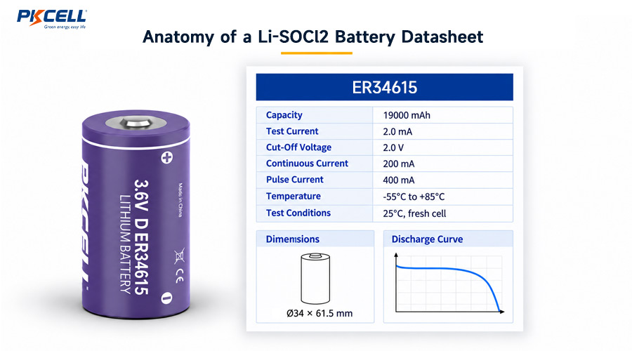
A lithium thionyl chloride battery datasheet can look simple: nominal voltage, capacity, maximum current, temperature range, and a discharge graph. The difficult part is understanding the conditions behind those numbers and deciding whether they match the real device.
For long-life meters, sensors, trackers, alarms, data loggers, and remote IoT equipment, a small difference in test current, cut-off voltage, temperature, pulse duration, or storage history can change how much of the rated energy is actually usable. This guide explains how to read a Li-SOCl2 battery datasheet without turning a catalog value into an unsupported field-life promise.
Need Help Interpreting a Battery Datasheet?
Send PKCELL your current profile, pulse duration, minimum system voltage, temperature range, storage time, target life, and enclosure limits. An engineer can help compare ER Energy, ER Power, and ER + HPC options.
Start With the Chemistry and Cell Construction
Li-SOCl2, also written as LiSOCl2, identifies lithium thionyl chloride chemistry. These are primary batteries, which means they are not rechargeable. They are commonly selected for long-duration industrial devices because of their high nominal voltage, high energy density, low self-discharge, and suitability for extended standby operation.
However, two cells with the same chemistry and external size may be optimized for different loads:
- Bobbin or ER Energy Type: designed primarily for high energy and long service under low continuous drain.
- Spiral or ER Power Type: designed for stronger current delivery, usually with a tradeoff in nominal capacity for the same approximate size.
- ER + HPC configuration: combines the long-term energy of a bobbin-type ER cell with a hybrid pulse capacitor that supports high-current events.
Before comparing capacities, confirm which construction the datasheet represents. PKCELL separates its ER Energy Type range from its ER Power Type range, helping engineers shortlist cells by load profile as well as physical size.
Li-SOCl2 Datasheet Terms Engineers Must Read Together
| Datasheet Field | What It Means | What It Does Not Prove | Engineering Check |
|---|---|---|---|
| Nominal voltage | A reference operating-voltage value for the chemistry and cell. | That the device will always receive this voltage under load. | Compare loaded voltage with regulator and brownout limits. |
| Nominal capacity | Charge delivered under stated discharge conditions. | Usable capacity in every device, temperature, or current profile. | Read test current, temperature, and cut-off voltage. |
| Cut-off voltage | The voltage at which the capacity test ends. | That your electronics can operate down to the same voltage. | Use the higher practical limit: battery test cut-off or device threshold. |
| Maximum continuous current | An upper continuous-load limit under specified conditions. | That operation at this current delivers nominal capacity or long life. | Review voltage, heat, capacity loss, and duty cycle. |
| Maximum pulse current | A short-duration current capability defined by test conditions. | Unlimited pulse length, unlimited repetitions, or cold-start success. | Match amplitude, duration, frequency, temperature, and minimum voltage. |
| Operating temperature | The permitted operating envelope. | Equal capacity and pulse performance across the whole range. | Inspect curves and test at application extremes. |
| Self-discharge / shelf life | Expected retention under stated storage conditions. | Guaranteed device runtime after uncontrolled storage. | Include storage temperature, duration, and passivation risk. |
1. Nominal Capacity: Read the Conditions After the Number
Capacity, normally expressed in milliamp-hours or amp-hours, is the most visible number on a lithium thionyl chloride battery datasheet. It is also one of the easiest to misuse.
A statement such as “2,400mAh” is incomplete without its measurement conditions. For example, a PKCELL ER14505 specification defines nominal capacity at a stated low discharge current and continues the test to a 2.0V end voltage at approximately room temperature. That result describes a controlled test, not every possible device.
Four questions to ask about capacity
- What discharge current was used? A low test current may provide more accessible capacity than a heavier application load.
- What was the cut-off voltage? A test that runs to 2.0V may access energy that a 2.7V or 3.0V device cannot use.
- What was the test temperature? Room-temperature capacity does not automatically represent cold-field performance.
- Was the load continuous or intermittent? Recovery periods and pulse behavior can change the voltage profile.
Rated capacity is a result produced under defined conditions. Usable capacity is the energy your device can access before it reaches its real electrical limit.
Datasheet Example: What “2,400mAh” Really Says
PKCELL lists the AA-size ER14505 at 2,400mAh nominal capacity. The associated specification defines capacity using a particular low-current discharge to 2.0V at 23 ± 2°C. If the final product draws higher current, operates at low temperature, or shuts down above 2.0V, its usable capacity can be lower than the headline value.
2. Cut-Off Voltage: The Boundary Between Stored and Usable Energy
Cut-off voltage is the end point used for a discharge or capacity test. It matters because a battery can still contain chemical energy after the product has stopped operating.
Suppose a datasheet capacity is measured down to 2.0V, but the device’s power-management circuit resets at 2.7V. The device cannot use the portion of the discharge curve below 2.7V. Its effective cut-off is therefore determined by the system, not only by the battery test.
Map every voltage threshold in the power path
- Battery voltage under the expected load.
- Minimum input voltage of the regulator or DC/DC converter.
- Microcontroller brownout and reset thresholds.
- Minimum operating voltage of radios, GNSS modules, sensors, memory, and actuators.
- Voltage loss across protection, wiring, connectors, holders, and fuses.
The most restrictive element may change by operating mode. A sleeping controller might operate at a lower voltage than a modem during network attachment. This is why loaded minimum voltage is often more important than open-circuit voltage.
3. Continuous Current: A Limit, Not a Recommended Design Point
Maximum continuous discharge current describes a current ceiling under specified conditions. It should not automatically become the product’s normal operating current.
Running near the maximum can increase voltage drop, reduce accessible capacity, and shorten operating life. For a long-life industrial design, compare the expected continuous or average current with both the datasheet limit and the discharge curves. A battery selected for ten years of standby is normally operated far below its maximum current rating.
Also separate average current from continuous current. A device that sleeps at microamp-level current and transmits intermittently may have a low average current but still impose pulses that exceed the intended capability of an energy-type cell.
4. Pulse Current: The Number Needs a Time Definition
A pulse-current rating is meaningful only when pulse duration, repetition rate, temperature, initial state, load voltage, and recovery time are known. “400mA pulse” does not tell an engineer whether the pulse lasts milliseconds or seconds, whether it repeats once per day or every minute, or how low the terminal voltage is allowed to fall.
For every pulse rating, ask:
- How long is the pulse?
- How often does it repeat?
- What background current flows between pulses?
- What is the minimum voltage during the pulse?
- At what temperature was the value established?
- Was the cell fresh, aged, stored, or partially discharged?
- How quickly does voltage recover before the next event?
Wireless transmission, GNSS startup, flash writes, valves, motors, alarms, and sensor heaters can all create short high-current events. If the pulse exceeds the practical capability of an ER Energy cell, consider the hybrid pulse capacitor series or compare a power-type construction.
5. Test Conditions: Where the Real Specification Lives
Test conditions may appear in a table remark, graph label, footnote, or separate test-method section. These details determine whether two apparent specifications can be compared fairly.
| Test Condition | Why It Changes the Result | What to Match in the Device |
|---|---|---|
| Discharge current | Higher current can increase voltage sag and reduce accessible capacity. | Sleep, active, average, continuous, and peak currents. |
| Ambient temperature | Cold increases impedance; heat can accelerate aging and self-discharge. | Installation, storage, seasonal, and enclosure temperatures. |
| End voltage | A lower end voltage counts more delivered capacity. | System brownout, regulator dropout, and peripheral limits. |
| Load type | Continuous, resistive, pulsed, or power-controlled loads stress the cell differently. | Real electronics and duty cycle. |
| Storage history | Time and temperature influence aging and passivation. | Factory inventory, shipping, distributor storage, and pre-installation time. |
| Cell age / depth of discharge | Internal resistance and voltage response can change over life. | Beginning-, middle-, and end-of-life operation. |
6. Discharge Curves: Read the Axes Before the Shape
A discharge curve typically plots voltage against time, capacity, or percentage discharged. Multiple lines may represent different currents or temperatures. Before drawing a conclusion, identify:
- The horizontal-axis unit: hours, days, delivered capacity, or state of discharge.
- The vertical-axis scale and the test cut-off voltage.
- The current and temperature assigned to each curve.
- Whether the graph shows constant current, constant resistance, or pulse loading.
- Whether the curve represents typical performance rather than a guaranteed minimum.
A flat-looking voltage plateau is useful, but it can make remaining-life estimation difficult. The system may see little warning before voltage approaches the knee of the discharge curve. Device designers should not assume a simple voltage reading provides an accurate fuel gauge for a lithium thionyl chloride battery.
7. Temperature Range: Permission Is Not Performance
An operating range tells you where the battery may be used within its specified limits. It does not mean the cell delivers the same capacity, pulse voltage, or recovery behavior at every point in that range.
At low temperature, internal resistance generally increases, making voltage sag more severe and reducing the energy accessible above the device cut-off. At elevated temperature, immediate power behavior may appear stronger, but prolonged heat can accelerate self-discharge and aging. The PKCELL temperature guide explains why current capability and usable capacity must be evaluated together.
Qualification should reproduce the cell’s real thermal environment, including enclosure heating, solar loading, winter soak, shipping exposure, and the temperature at the moment of the highest-current event.
8. Passivation and Voltage Delay
Li-SOCl2 chemistry naturally forms a passivation layer on the lithium anode. This behavior helps limit unwanted reaction and supports low self-discharge, but it can also increase initial impedance after storage or long low-current standby.
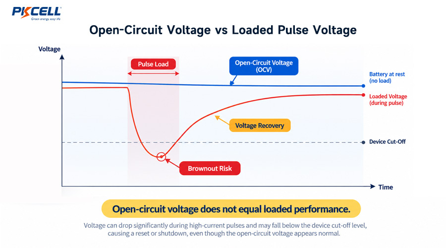
When the device suddenly wakes, terminal voltage may dip and then recover as the cell responds to the load. A normal open-circuit voltage therefore does not prove the battery can start a modem, drive a valve, or remain above the system cut-off at low temperature.
Read the Li-SOCl2 passivation guide for recommended loaded-voltage, first-start, storage, and environmental tests. The related article on why OCV is not enough provides a practical device-level testing framework.
9. Mechanical, Terminal, and Safety Information
Electrical performance is only part of the datasheet. Review dimensions, tolerances, weight, polarity, sealing, terminal options, and transport documentation before approving a component.
Mechanical checks
- Maximum cell diameter and length, not only nominal size.
- Holder contact pressure and vibration behavior.
- Axial leads, solder tabs, wires, connector orientation, and insulation.
- Clearance for assembly, service, swelling tolerance, and protective components.
Safety checks
- Confirm the cell is primary and must not be recharged.
- Do not short-circuit, crush, disassemble, incinerate, or use outside specified limits.
- Review required UN38.3, MSDS, transport, market, and customer documentation for the exact cell or pack.
- Confirm pack-level protection, fusing, isolation, and parallel-cell controls with the supplier.
From Datasheet to Device: A Practical Validation Process
- Record the complete load profile. Include sleep, sensing, processing, memory, communication, retries, alarms, and actuators.
- Identify every voltage threshold. Include regulator dropout, brownout reset, radio minimum voltage, and wiring loss.
- Shortlist the construction. Compare ER Energy, ER Power, or ER + HPC based on energy and current requirements.
- Estimate life conservatively. Apply realistic allowances for cut-off voltage, temperature, self-discharge, storage, and aging.
- Test loaded voltage. Measure the minimum voltage and recovery during the real pulse, not only OCV.
- Test environmental corners. Include cold start, high-temperature storage, first activation after storage, and end-of-life conditions.
- Validate the final assembly. Use production-intent wiring, connector, holder, protection, enclosure, firmware, and communications.
PKCELL’s Primary Lithium Battery Solution Hub organizes recommended chemistry and models by industrial application. For wireless devices with demanding pulse loads, the IoT ER + HPC solution range provides another starting point.
Common Li-SOCl2 Datasheet Reading Mistakes
Comparing capacities measured under different conditions
Two amp-hour ratings are not directly comparable unless discharge current, end voltage, temperature, and test method are aligned.
Treating maximum pulse current as a universal guarantee
A pulse specification without duration, repetition, minimum voltage, and temperature context cannot prove device compatibility.
Assuming the full operating range delivers full capacity
The cell may be permitted to operate at an extreme temperature while providing less accessible energy or weaker pulse performance there.
Using OCV as the only incoming inspection
OCV is useful for screening, but it cannot reveal loaded voltage sag, passivation-related delay, or recovery behavior.
Calculating life from nominal capacity alone
This formula is only a first-pass estimate. A production design must account for usable capacity above device cut-off, storage, self-discharge, temperature, pulse losses, aging, and design margin.
Frequently Asked Questions
What does nominal capacity mean on a Li-SOCl2 battery datasheet?
It is the charge delivered under the manufacturer’s stated test conditions. Read the associated discharge current, temperature, and cut-off voltage before applying the value to a device.
Why does cut-off voltage affect usable battery capacity?
A device that shuts down above the datasheet test cut-off cannot access all capacity counted in that test. The system’s highest practical voltage threshold determines how much of the discharge curve is usable.
Is maximum pulse current the same as maximum continuous current?
No. Continuous current is sustained, while pulse current applies for a limited duration under defined conditions. Pulse amplitude, length, repetition, temperature, and loaded voltage all matter.
Why can a Li-SOCl2 battery show normal voltage but fail under load?
Open-circuit voltage does not measure dynamic current delivery. Internal resistance, low temperature, passivation, cell age, or state of discharge can cause voltage to fall below the device threshold when a load is applied.
When should engineers consider ER + HPC?
ER + HPC should be evaluated when a long-life device also requires substantial current pulses, such as cellular or LoRa transmission, GNSS startup, valve actuation, alarm output, or repeated cold-temperature pulses.
Can a lithium thionyl chloride battery be recharged?
No. Standard Li-SOCl2 batteries are primary, non-rechargeable cells. Attempting to recharge them is unsafe.
Conclusion: A Datasheet Is the Start of Selection
A Li-SOCl2 battery datasheet is most useful when every headline number is connected to its test conditions. Nominal capacity must be read with discharge current, temperature, and cut-off voltage. Pulse current must be read with duration, repetition, loaded voltage, and cell history. The operating range must be separated from guaranteed performance at its extremes.
Use the datasheet to create a technically credible shortlist, then validate the exact cell or pack in the final product across storage, temperature, pulse, communications, and end-of-life conditions.
Share Your Application Conditions With PKCELL
For model selection, datasheets, samples, custom leads or connectors, ER + HPC evaluation, and OEM quotations, send the complete device profile to PKCELL.
Post time: Sep-20-2026


