

Battery Selection for Railway Trackside Monitoring Sensors
Railway trackside monitoring sensors help infrastructure operators observe equipment condition, identify developing faults and collect field data without requiring continuous manual inspection. From vibration sensors and bearing-condition monitors to environmental loggers and remote diagnostic nodes, these devices may need to operate for extended periods with limited access to battery replacement.
Selecting a railway trackside sensor battery requires more than matching nominal voltage and capacity. Measurement frequency, standby current, wireless transmission, temperature changes, mechanical vibration and maintenance access all influence the final battery configuration. This guide explains how equipment manufacturers and industrial sensor OEMs can evaluate these requirements systematically.
1. Trackside Condition Monitoring Applications
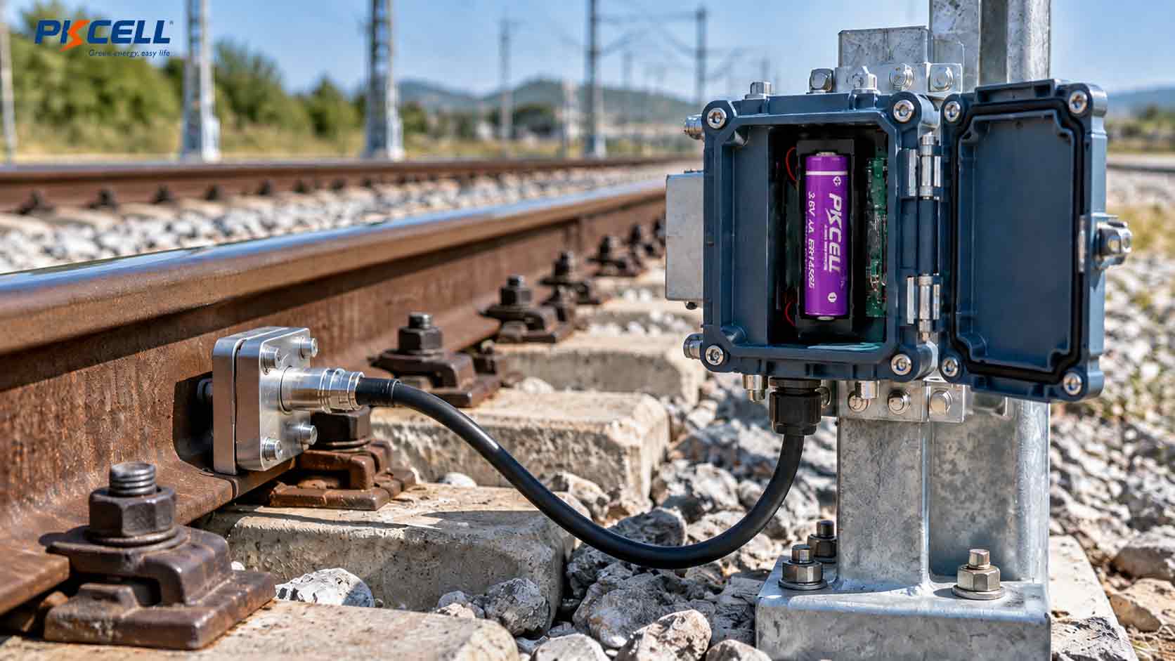
Railway infrastructure includes distributed equipment installed beside tracks, near bridges and tunnels, around trackside cabinets and at other locations where remote condition information can support maintenance planning. Battery-powered sensors can be useful when local power is unavailable, difficult to route or expensive to maintain.
The electrical requirements depend on what the device measures and how often it reports information. A simple environmental logger may remain asleep between periodic measurements, while a vibration-monitoring node may collect high-rate data for a short period before returning to a low-power state.
Typical Trackside Monitoring Applications
- Track and infrastructure condition monitoring: Collects selected vibration, displacement or environmental measurements to support infrastructure inspection and maintenance.
- Remote equipment condition monitoring: Records operating parameters from non-safety-critical auxiliary equipment and reports abnormal conditions to a maintenance platform.
- Environmental monitoring: Measures temperature, humidity, water ingress or other site conditions around trackside equipment, cabinets and remote infrastructure.
- Wireless diagnostic nodes: Collect sensor readings, store event data and transmit periodic reports through an appropriate industrial wireless network.
- Remote inspection and data logging: Records field measurements for later retrieval or scheduled communication where continuous connectivity is not necessary.
A battery for railway IoT sensors must support the actual monitoring sequence rather than an assumed generic railway load. A temperature logger, a vibration sensor and a wireless diagnostic terminal may have very different energy and pulse-current requirements.
For applications involving long unattended periods, PKCELL’s Primary Lithium Battery Solution Hub provides a starting point for comparing Li-SOCl2 cells, pulse-assisted solutions and customized battery packs for industrial monitoring devices.
2. Battery Requirements Under Temperature Changes and Vibration
Railway trackside equipment may experience seasonal temperature changes, direct solar heating, rain, condensation, mechanical vibration and repeated thermal cycling. The battery must be evaluated within the actual device enclosure and installation environment.
Evaluate the Complete Temperature Profile
Define the minimum and maximum temperatures that the battery may experience during storage, transportation and field operation. The temperature inside a sealed enclosure can differ substantially from the surrounding air, particularly when equipment is exposed to sunlight or installed in an enclosed cabinet.
Low temperatures can increase effective battery impedance and reduce available output under load. High temperatures can accelerate aging and change long-term performance. Consequently, the cell’s published operating range should not be treated as proof that the finished sensor will operate correctly throughout that range.
Consider Vibration and Mechanical Integration
Trackside installations may be exposed to vibration transmitted through support structures, equipment cabinets and nearby infrastructure. Mechanical reliability depends on the complete assembly, including the battery holder, pack housing, cable routing, connector retention and mounting hardware.
- Secure the battery against movement inside the enclosure.
- Choose wire lengths and connector types suitable for the installation.
- Provide strain relief to reduce stress on cable terminations.
- Prevent battery movement from damaging insulation or nearby electronics.
- Evaluate the finished assembly under the project’s specified vibration and shock test conditions.
Check Enclosure Protection and Maintenance Access
A protective housing can help shield the battery from environmental exposure, but enclosure performance depends on its design, sealing, connectors and installation. Confirm the required ingress protection, chemical compatibility and applicable environmental specifications for the complete product.
Also consider how technicians will access the battery. A pack that fits inside the enclosure but requires extensive disassembly during replacement may increase maintenance time and lifecycle cost.
3. Standby Power and Wireless Communication Loads
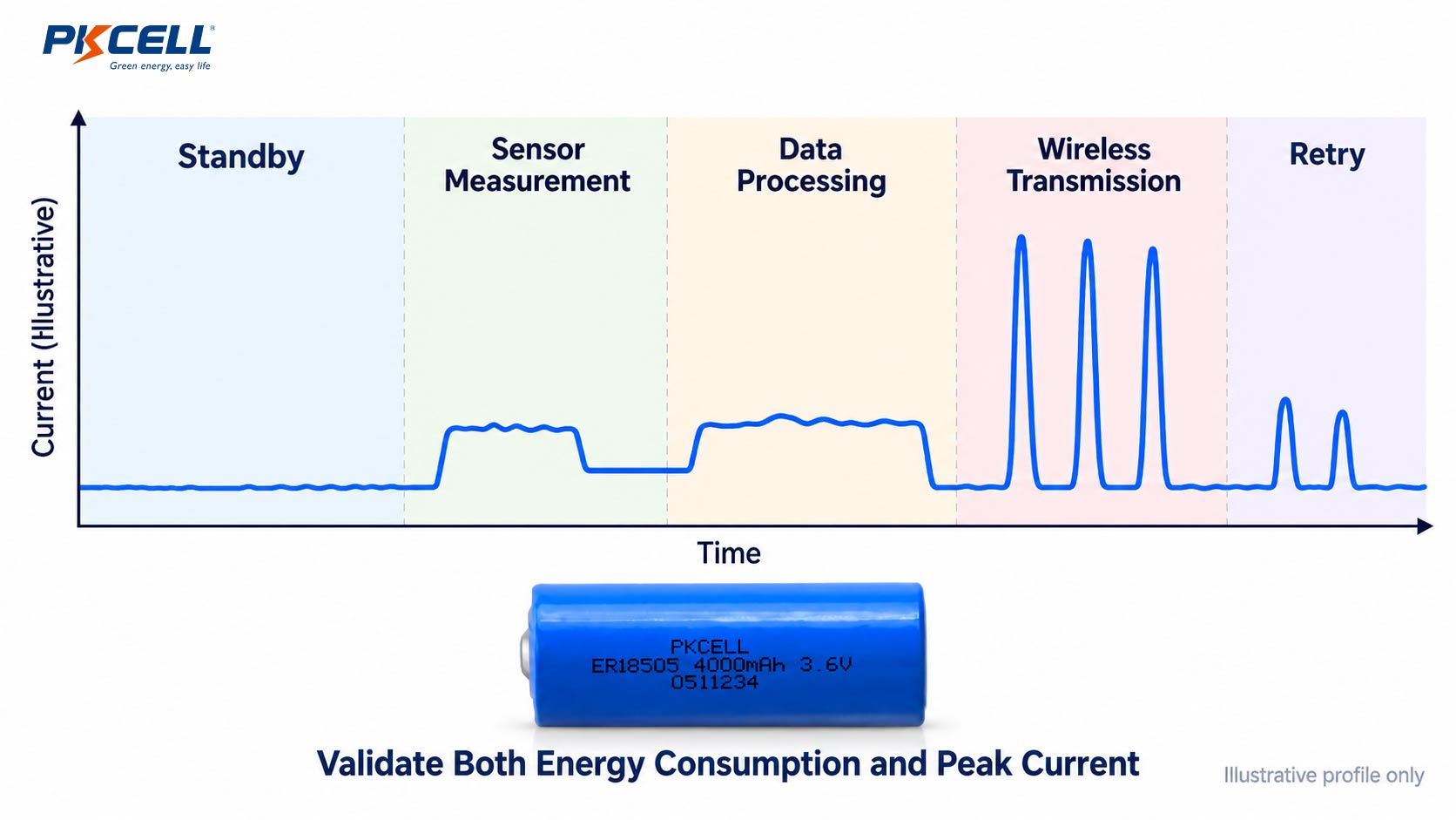
Many remote monitoring devices spend most of their service life in standby. However, their current consumption can rise significantly during sensor acquisition, data processing, memory operations, wireless startup and transmission.
For this reason, the railway monitoring sensor battery must be assessed using both its long-term energy demand and its ability to maintain the required voltage during active events.
Build an Operating-State Energy Budget
Start by dividing the device’s operation into measurable states. Record the current and duration of each state using the production-intent electronics and firmware whenever possible.
- Standby: the processor and essential circuits remain in low-power mode.
- Sensor wake-up: the sensing element and interface circuits start operating.
- Measurement: the device acquires and processes data.
- Storage: the controller writes measurements or event records to memory.
- Communication: the radio initializes, connects to the network and transmits data.
- Retry: unsuccessful transmission attempts extend the active period and consume additional energy.
Multiply the energy consumed by each operating cycle by the expected number of cycles during the deployment period. Add the background energy consumed between cycles, along with the expected contribution from self-discharge and other relevant losses.
Distinguish Average Energy from Peak Current
A wireless transmission may account for only a small portion of total energy consumption but still determine whether the battery can power the device reliably. Radio startup, network registration and data transmission can produce short current peaks.
The approximate voltage drop across the battery and connections can be expressed as:
This relationship provides an initial screening estimate. Actual battery behavior is dynamic and depends on cell construction, temperature, discharge history, passivation and pulse duration. The minimum loaded voltage must remain above the device’s operating threshold.
When Should a Pulse-Assisted Battery Be Considered?
For long-standby devices with relatively demanding wireless transmission loads, an ER-series Li-SOCl2 cell combined with a Hybrid Pulse Capacitor (HPC) may be worth evaluating. The cell supplies long-term energy while the pulse-assist component helps support short-duration power demand.
Explore PKCELL’s primary lithium battery pack options to compare standard ER packs and customized configurations. For pulse-heavy devices, the final design should account for peak current, pulse duration, recovery time, event frequency and capacitor leakage.
4. Battery Cell vs. Custom Pack Selection
Choosing between a single cell and a customized pack depends on voltage, usable capacity, peak-current requirements, available space, wiring interfaces and the maintenance strategy. The most appropriate solution is the one that satisfies the complete device specification.
| Battery option | Potential application fit | Key engineering checks |
|---|---|---|
| ER14505 Li-SOCl2 cell | Compact, low-power monitoring nodes with limited installation space | Usable capacity, operating temperature, pulse current and minimum voltage |
| ER18505 Li-SOCl2 cell | Devices needing a different balance of cell dimensions and stored energy | Actual current profile, mechanical fit and expected maintenance interval |
| ER26500 or ER34615 Li-SOCl2 cell | Equipment with sufficient space for a larger cylindrical cell and a higher energy requirement | Dimensions, mass, usable capacity, load profile and enclosure integration |
| ER + HPC battery pack | Long standby combined with demanding wireless or event-driven pulses | Pulse characteristics, recovery time, leakage and repeated-event behavior |
| Customized primary lithium battery pack | Devices requiring special voltage, dimensions, connectors or mounting arrangements | Cell configuration, wiring, mechanical retention and complete-pack validation |
When a Standard ER Cell May Be Sufficient
A standard ER-series Li-SOCl2 cell is a potential starting point when the sensor has low average current, infrequent measurement events and a communication load within the cell’s specified capability. The available product range includes different cell sizes and capacities to accommodate different energy and space requirements.
Visit the Primary Lithium Battery Solution Hub to review application-based battery directions before selecting a model. Nominal capacity alone should not be used to predict field runtime.
When a Custom Battery Pack Is More Appropriate
A customized pack can simplify integration when the monitoring device requires a particular operating voltage, cable length, connector, mounting structure or series-parallel configuration. The design should also address insulation, connector retention and any applicable environmental requirements.
PKCELL provides customized primary lithium battery packs for OEM applications. Share the device’s electrical and mechanical requirements to determine whether a standard cell or a pack-level solution is the more appropriate direction.
5. Field Validation and Maintenance Planning
A battery-life calculation is a planning tool, not a guarantee of field performance. Validation should reproduce the complete operating sequence under the specified electrical, environmental and mechanical conditions.
Step 1: Measure the Actual Current Profile
Measure standby current, sensor startup, acquisition, processing, memory writes, radio startup and transmission. Include retries and other credible events that may extend the active period.
Step 2: Establish the Voltage Limits
Document the minimum operating voltage and reset threshold for each relevant subsystem. Measure voltage at the battery terminals during the highest expected load, including the resistance introduced by wires and connectors.
Step 3: Test at Temperature Extremes
Evaluate the complete device at the specified minimum and maximum operating temperatures. Allow the assembly to stabilize before testing, and repeat critical measurements with batteries representative of the intended end-of-life condition.
Step 4: Test Mechanical and Environmental Conditions
Verify battery retention, cable routing, connector security and enclosure sealing. Where required, perform vibration, shock, humidity and temperature-cycle tests according to the project’s defined test plan.
Step 5: Validate Communication Reliability
Simulate the expected wireless reporting sequence, including weak-signal conditions, delayed network access and repeated transmissions where these are credible for the deployment. Confirm that the battery voltage does not fall below the system’s required operating threshold.
Step 6: Plan for the Complete Maintenance Interval
Use the measured energy budget, usable capacity, self-discharge, temperature effects and an appropriate reserve to estimate service life. The maintenance plan should also consider access cost, inspection frequency, battery replacement time and the consequence of losing monitoring data.
Information to Prepare Before Battery Selection
- Required operating voltage and minimum system voltage.
- Standby current and complete measurement-cycle duration.
- Peak current, pulse duration and event frequency.
- Wireless technology, reporting interval and retry behavior.
- Minimum and maximum operating temperatures.
- Specified vibration, shock and enclosure requirements.
- Target service life and battery replacement interval.
- Available installation space, mounting method and connector details.
- Applicable project standards and intended equipment classification.
- Prototype quantity and estimated annual demand.
For a custom project, PKCELL’s custom battery pack quotation checklist can help organize the electrical, environmental, mechanical and commercial information required for an engineering review.
Common Battery Selection Mistakes
- Selecting a battery based on nominal capacity without measuring the complete device current profile.
- Ignoring wireless startup and retry-related voltage dips.
- Assuming the battery’s temperature rating proves the performance of the complete sensor assembly.
- Overlooking vibration, connector retention and mechanical mounting.
- Setting a maintenance interval from an ideal runtime estimate without accounting for usable capacity and design reserve.
- Assuming a general-purpose battery is approved for safety-critical railway signalling or train-control equipment.
- Failing to validate the finished device with the selected battery configuration and production-intent firmware.
Frequently Asked Questions
What is a suitable battery for railway trackside monitoring sensors?
For low-power, long-duration monitoring, an ER-series Li-SOCl2 cell can be a useful starting point. Devices with demanding wireless pulses may require a power-oriented cell or an ER + HPC configuration. The final choice depends on current profile, voltage limits, temperature, available space and target service life.
How does vibration affect battery pack selection?
Vibration can stress cell holders, wiring, soldered joints, connectors and enclosure mounts. The finished battery assembly should be mechanically secured and validated against the vibration and shock conditions defined for the application.
Can Li-SOCl2 batteries support wireless railway monitoring sensors?
They may be suitable for some non-safety-critical remote monitoring devices, particularly when average current is low. The cell’s pulse capability, passivation behavior, temperature performance and the radio’s minimum voltage requirement must be checked. Some applications may benefit from a pulse-assisted pack.
Should a battery pack be customized for trackside equipment?
A custom pack is worth evaluating when the device requires a particular voltage, capacity, connector, wire length, mounting structure or cell configuration. The decision should be based on the complete mechanical and electrical specification.
Can these battery options be used in railway signalling systems?
This article addresses monitoring and diagnostic applications, not automatic approval for safety-critical signalling, interlocking or train-control functions. Such applications require a separate review of system-level safety requirements, applicable railway standards, qualification and approval.
Choose a Battery Around the Monitoring Duty Cycle
A reliable railway trackside sensor battery must provide sufficient usable energy for the required maintenance interval while maintaining the voltage needed during sensing, processing and communication. Temperature changes, vibration, enclosure design and field access should be included in the same engineering assessment.
By measuring the complete operating cycle and validating the finished device under representative conditions, infrastructure monitoring equipment manufacturers can make more defensible battery choices and reduce avoidable field maintenance.
PKCELL supports primary lithium cells and customized battery pack development for industrial monitoring and remote sensing applications. The appropriate configuration should be selected against the device’s actual requirements and validated before deployment.
Discuss Your Railway Monitoring Battery Requirements
Developing a trackside condition monitoring sensor, remote diagnostic node or railway infrastructure data logger? Send PKCELL your voltage requirements, current profile, temperature range, vibration requirements, target service life and available battery space.
Include your connector details, wireless reporting profile, prototype quantity and estimated annual demand. These inputs will help the team review whether a standard ER-series cell or a customized primary lithium battery pack is the more appropriate starting point.
Request a Battery Recommendation
Explore Custom Battery Packs
Post time: Oct-20-2026


