

Lithium thionyl chloride batteries are widely used in long-life IoT, smart metering, industrial sensing, and remote monitoring applications. However, OEM engineers may encounter a confusing problem during testing or field deployment: the battery appears to have normal voltage, but the device fails during first startup, wireless transmission, valve actuation, or another high-current event.
Key takeawayLiSoCl2 battery passivation is not simply a battery defect. It is a natural characteristic of lithium thionyl chloride chemistry that helps reduce self-discharge and support long shelf life. The engineering challenge is to manage voltage delay under the actual device load, especially after long storage, long low-current standby, low temperature, or high pulse current.
This guide explains what passivation means for OEM device design, how it appears in real testing, how to measure it, and when to consider ER Power Type cells, pulse support, or ER + HPC battery packs.
1. What Is LiSoCl2 Battery Passivation?
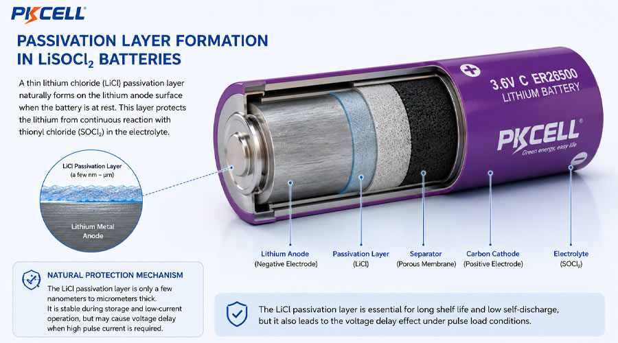
Passivation is a natural phenomenon in lithium thionyl chloride batteries. When lithium metal contacts the thionyl chloride electrolyte, a thin protective layer forms on the lithium anode surface. This layer is usually described as a lithium chloride-based passivation layer.
PKCELL has an existing technical article, What is the Passivation of a LiSoCl2 Battery? How to Remove?, which explains the basic concept. This article goes further from an OEM design perspective: how passivation affects startup, pulse current, storage, field reliability, and battery pack selection.
Basic Definition
Why Passivation Is Not Always Bad
Passivation is one reason LiSoCl2 batteries can achieve low self-discharge and long shelf life. Without this protective behavior, long-term primary battery applications such as smart meters, remote sensors, and utility devices would be much more difficult to support.
OEM design noteThe problem is not the existence of passivation. The problem is uncontrolled voltage delay under the real load profile. OEM engineers should manage passivation through cell selection, storage control, pulse support, firmware startup strategy, and validation testing.
2. How Passivation Causes Voltage Delay
What Is Voltage Delay?
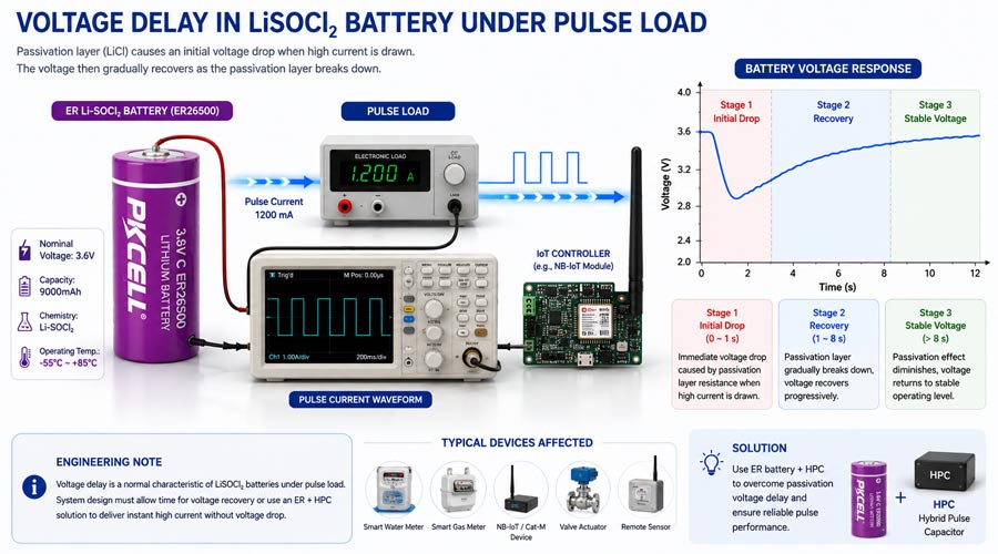
Voltage delay means the battery voltage drops or stays lower than expected when the load is first applied, then gradually recovers as the passivation layer breaks down or stabilizes under current flow.
Typical Voltage Delay Events
- A device wakes from long sleep and starts a wireless module.
- An NB-IoT modem starts network attach or data transmission.
- A LoRaWAN transmitter sends the first packet after storage.
- A GNSS module starts positioning after a long standby period.
- A smart gas or water meter drives a valve motor.
- An alarm device activates high-power transmission.
Why Voltage Delay Happens
The passivation layer increases initial impedance. When a sudden current demand appears, the voltage may drop. If the device minimum operating voltage is high, or if the pulse current is large, the electronics may reset before the voltage recovers.
3. Which Applications Are Most Affected by Passivation?
Long-Life Low-Current IoT Devices
Passivation is more visible in devices that stay at very low current for long periods and then suddenly wake up for communication or measurement. Examples include smart meters, remote sensors, parking sensors, environmental monitoring devices, industrial telemetry units, data loggers, and security devices.
Devices Stored for a Long Time Before Installation
Utility meter projects, distributor inventory, emergency equipment, export shipments, and industrial spare parts may remain in storage for months before activation. The first startup after storage should be included in the validation plan.
Devices with Sudden High-Current Pulses
Communication Pulses
- NB-IoT transmission
- LTE-M transmission
- LoRaWAN uplink
- Wireless retry under weak signal
- Alarm transmission
Device Load Pulses
- GPS / GNSS startup
- Valve actuation
- Sensor heating element
- Motor startup
- Cold-start operation
Cold-Environment Applications
Low temperature increases impedance and makes voltage drop more obvious. The combination of passivation, low temperature, and high pulse current is one of the highest-risk conditions for long-life primary battery devices.
4. Main Factors That Increase Passivation Risk
5. How Passivation Appears in Real OEM Testing
Common Symptoms
- First startup failure after long storage.
- Modem reset during NB-IoT attach or upload.
- MCU brownout reset during wireless transmission.
- Failed LoRaWAN uplink after long sleep.
- Valve motor does not complete actuation.
- Battery open-circuit voltage appears normal, but loaded voltage drops suddenly.
- Voltage recovers after several seconds or after repeated controlled load pulses.
- The device works with fresh batteries but fails after storage or low-temperature exposure.
Example 1: Smart Meter After Long Storage
A smart gas or water meter may be assembled and stored for several months before installation. During first activation, the modem upload fails even though the battery voltage looks normal. This may indicate first-pulse voltage delay rather than insufficient capacity.
Example 2: NB-IoT Device in Weak Signal Area
NB-IoT attach and data upload can require high current. In weak signal areas, retry behavior increases pulse stress. A battery that works in a strong-signal lab may fail in a real field deployment if passivation and voltage drop were not considered.
Example 3: Valve-Control Meter at Low Temperature
A valve-control meter may need to drive a motor after long standby. Low temperature increases both battery impedance and mechanical load. Passivation, cold conditions, and motor startup current can combine to create a serious voltage drop risk.
6. How to Measure LiSoCl2 Battery Passivation
Why Open-Circuit Voltage Is Not Enough
Open-circuit voltage can look normal even when the battery struggles under load. OEM engineers should measure loaded voltage, minimum voltage during pulse, recovery time, and repeated pulse behavior.
Load Pulse Test
Data to Record
7. How to Reduce Passivation Risk in OEM Design
Choose the Right Cell Type
PKCELL provides both LiSoCl2 ER Energy Type batteries and LiSoCl2 ER Power Type batteries. ER Energy Type cells are suitable for long-life low-current applications, while ER Power Type cells are designed for stronger pulse capability than standard energy-type cells.
Avoid Sudden Full-Power Startup
Firmware can reduce passivation-related startup issues. Instead of powering the modem or valve immediately, the device can wake the MCU first, stabilize system voltage, delay high-current modules, and avoid unnecessary first-second peak current.
Add Pulse Support
- Use an appropriately sized capacitor or HPC when the device has pulse loads.
- Consider ER + HPC battery packs for NB-IoT, LoRaWAN, GNSS, valve, or alarm applications.
- Use lower-resistance wires, connectors, tabs, and welding processes.
- Choose a larger cell or ER Power Type cell if the application load requires it.
Control Storage and Activation Conditions
Define the maximum storage time before installation, avoid unnecessary high-temperature storage, test after simulated storage, and define incoming inspection or pre-conditioning procedures when needed.
8. ER Battery + HPC as a Solution for High-Pulse Applications
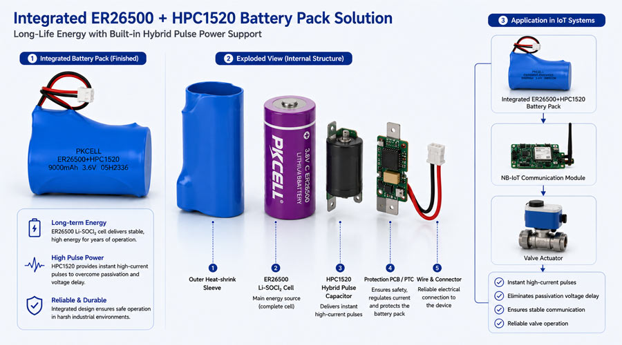
PKCELL’s IoT Battery Pack Solutions (ER + HPC) combine a bobbin-type LiSoCl2 cell with HPC technology for efficient energy storage and high-current pulse support. PKCELL also offers Hybrid Pulse Capacitor LiSoCl2 battery pack solutions for industrial and IoT applications.
Why HPC Helps
- The ER battery provides long-term energy.
- The HPC stores energy during low-load periods.
- The HPC helps deliver short high-current pulses.
- Pulse support reduces voltage drop during modem TX, valve actuation, GNSS startup, or alarm events.
- The ER cell is less directly stressed by short high-current bursts.
When ER + HPC Is Recommended
Communication Applications
- NB-IoT meters
- LoRaWAN trackers
- GPS / GNSS devices
- Wireless alarms
- Weak-signal remote sensors
Metering and Industrial Applications
- Smart gas meters
- Smart water meters
- Valve-control devices
- Cold-chain sensors
- Remote industrial monitoring
For detailed pulse design logic, see ER Battery + HPC Design Guide for High-Pulse IoT Applications.
9. Depassivation: What OEM Engineers Should and Should Not Do
What Is Depassivation?
Depassivation means reducing the effect of the passivation layer through a controlled load or conditioning process so the voltage stabilizes before real operation. It may be considered for devices stored for a long time before activation or for high-reliability systems with strict startup requirements.
Why It Must Be Controlled
Safety and quality warningDo not short-circuit LiSoCl2 batteries. Do not use random high-current loads or uncontrolled depassivation procedures. Any conditioning method should follow the battery supplier’s recommendation and be validated with the actual device load profile, temperature, and acceptance criteria.
Better Than Depassivation Alone: Design Prevention
- Select the right cell type and size.
- Use ER Power Type or ER + HPC when pulse current is significant.
- Design a staged firmware startup sequence.
- Control storage time and storage temperature.
- Validate first startup after simulated storage.
- Test at low temperature and end-of-life voltage.
10. Testing Checklist for OEM Projects
Incoming Battery Test
Device-Level Electrical Test
- Sleep current and active current.
- Peak pulse current and pulse duration.
- Minimum voltage during communication, GNSS, valve, or alarm events.
- Voltage recovery time after pulse.
- Brownout reset threshold and cut-off voltage.
- Repeated pulse behavior.
Environmental and Application Test
- Low-temperature startup and low-temperature pulse test.
- High-temperature storage and temperature cycling.
- Long storage simulation and first activation test.
- Real NB-IoT attach or LoRaWAN upload test.
- GNSS cold start test.
- Valve open and valve close test.
- Weak-signal retry simulation.
- End-of-life voltage simulation.
11. Common Mistakes OEM Engineers Should Avoid
Design Mistakes
- Treating passivation as a battery defect only.
- Selecting ER cells by capacity only.
- Ignoring device cut-off voltage.
- Ignoring low-temperature startup.
- Using too small a cell for high pulse current.
Testing Mistakes
- Testing only fresh batteries.
- Checking only open-circuit voltage.
- No real network test for NB-IoT or LoRaWAN.
- No first-start test after storage.
- No end-of-life validation.
12. Recommended PKCELL Solutions for Passivation-Sensitive Applications
ER Energy Type Batteries for Long-Life Low-Current DevicesRecommended for smart meters, remote sensors, data loggers, and low-current IoT modules where long life and low self-discharge are the main goals.
ER Power Type Batteries for Higher Pulse RequirementsRecommended when the device requires stronger pulse capability than a standard energy-type cell can provide. Suitable models may include ER14505M, ER26500M, ER34615M, and other ER Power Type cells.
ER + HPC Battery Packs for High-Pulse IoTRecommended for NB-IoT devices, LoRaWAN trackers, smart water meters, smart gas meters, valve-control devices, cold-chain trackers, and remote monitoring devices that need long-life energy plus stable pulse output.
View ER + HPC Battery Packs View Hybrid Pulse Capacitor Series View 3.8/4V Li-Capacitors
Custom Battery Packs for OEM ProjectsRecommended when the product requires wires, connectors, tabs, waterproof pack structure, special housing, multiple cells, certification support, or application-specific testing.
View Custom Primary Lithium Battery Packs View Primary Lithium Battery Solution Hub View Utility Meter Batteries
13. What Information Should You Provide to a Battery Supplier?
A passivation-sensitive design review requires more than a target capacity. Before requesting samples, provide the following information.
Need help reducing voltage delay risk?Share your load profile, storage condition, operating temperature, and pulse current requirement with PKCELL. Our engineering team can help recommend the right ER cell, ER Power Type battery, or ER + HPC battery pack for your OEM device.
Request Battery Recommendation View ER + HPC Solutions Explore LiSoCl2 Batteries
14. FAQs About LiSoCl2 Battery Passivation
Conclusion: Passivation Should Be Managed at the Design Stage
LiSoCl2 passivation is not simply a problem to fix after failure. It is a natural part of the chemistry that helps enable long shelf life and low self-discharge, but it must be considered during OEM device design.
Open-circuit voltage alone is not enough. Engineers should test loaded voltage, first startup after storage, low-temperature pulse performance, real modem behavior, valve actuation, and end-of-life conditions. When high pulse current is part of the application, ER Power Type batteries or ER + HPC battery packs may be more reliable than capacity-based selection alone.
Related PKCELL Resources
- What is the Passivation of a LiSoCl2 Battery? How to Remove?
- LiSoCl2 Battery Series
- LiSoCl2 ER Energy Type Batteries
- LiSoCl2 ER Power Type Batteries
- IoT Battery Pack Solutions (ER + HPC)
- Hybrid Pulse Capacitor Series
- 3.8/4V Li-Capacitors
- Custom Primary Lithium Battery Packs
- How to Calculate Battery Life for LoRaWAN and NB-IoT Devices
- ER Battery + HPC Design Guide for High-Pulse IoT Applications
Sources and Further Reading
Post time: Jul-08-2026


