

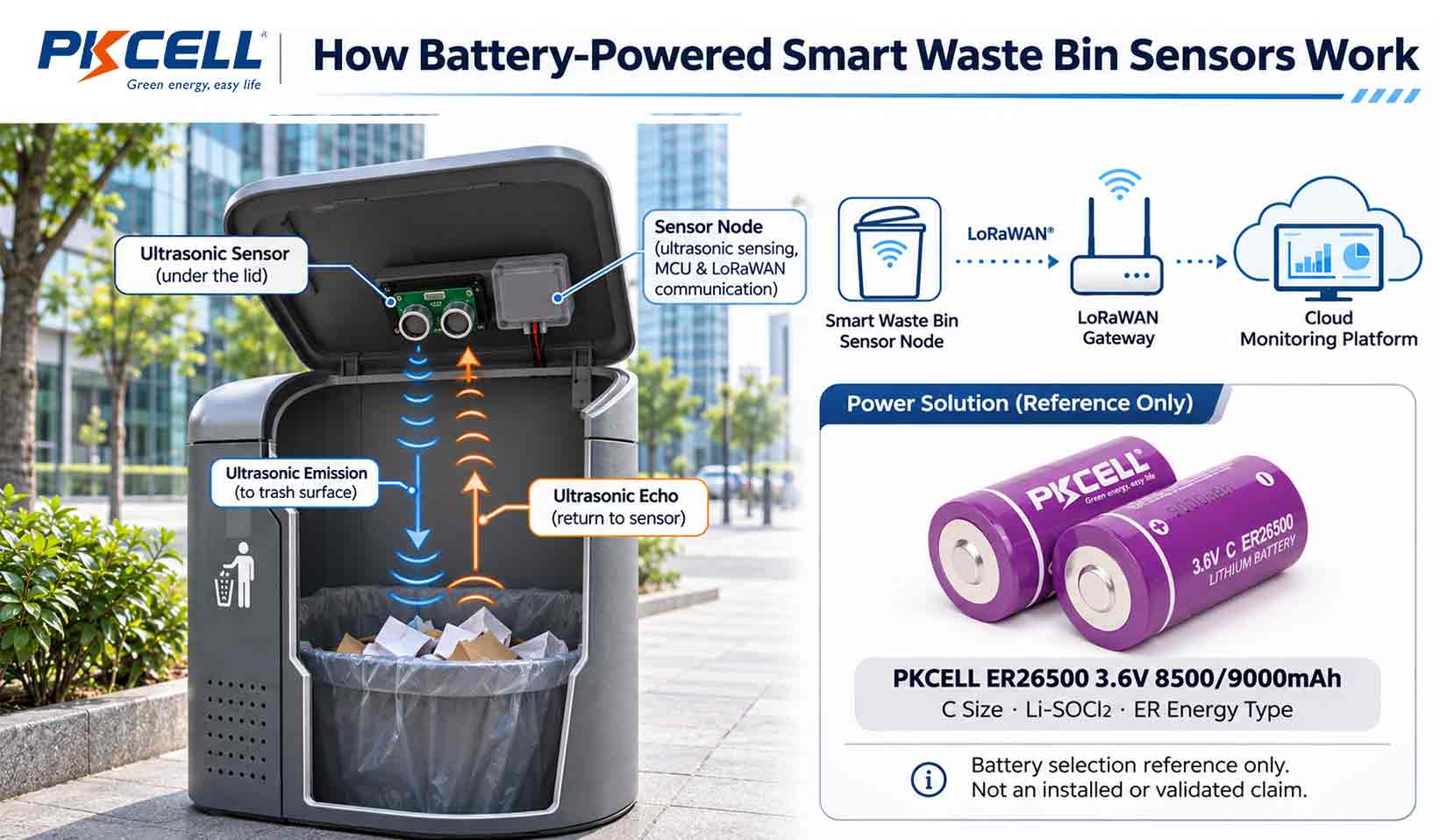
Traditional waste collection often follows fixed schedules, even though containers in busy commercial areas, public spaces, and residential districts fill at very different rates. Battery-powered smart waste bin sensors help operators monitor actual fill levels, identify containers that need attention, and plan collection more efficiently.
A typical ultrasonic smart bin sensor combines distance measurement, embedded processing, and wireless reporting. Its battery must support each activity while keeping maintenance requirements manageable.
How does a battery-powered smart waste bin sensor work?
- An ultrasonic transducer sends a sound pulse toward the waste surface.
- The sensor measures the time taken for the echo to return.
- A controller converts the distance into an estimated fill percentage.
- A wireless module reports the reading to a gateway or cellular network.
- The device returns to a low-power state until the next measurement or reporting event.
This article focuses on standalone battery-powered monitoring sensors, not motorized compactors or automatic lid actuators, which require separate power-system analysis.
1. How Ultrasonic Fill-Level Detection Works
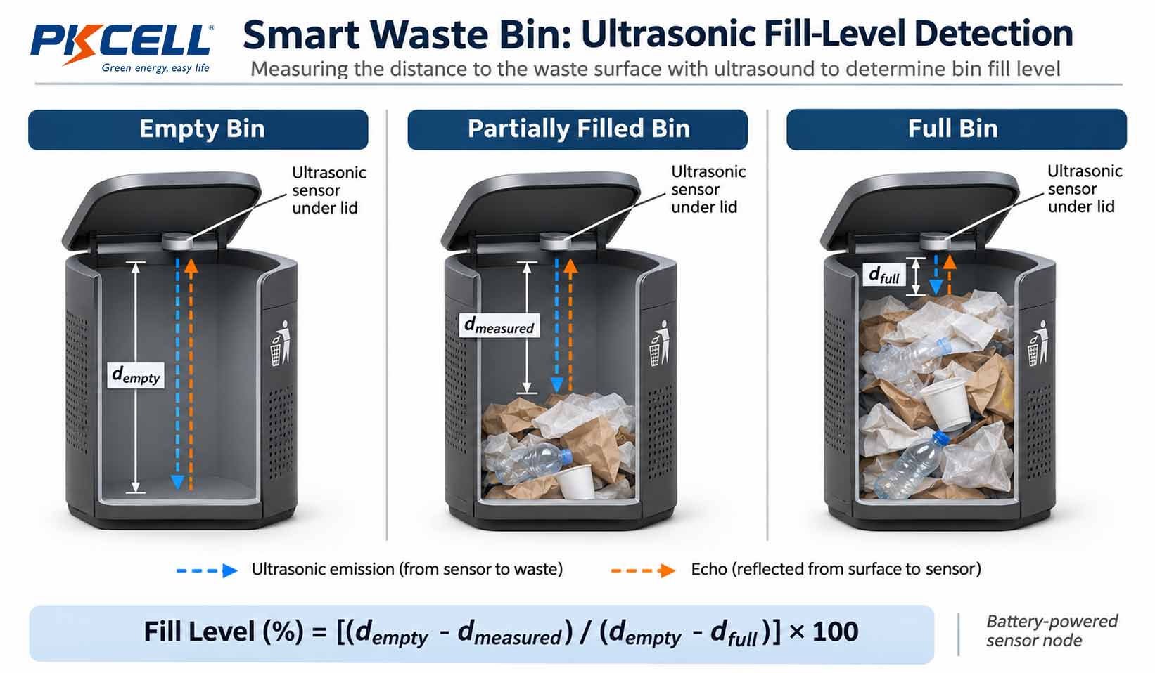
An ultrasonic sensor is usually mounted beneath the waste-bin lid and faces downward. It measures the distance to the upper surface of the waste rather than directly measuring weight or volume.
STEP 01
Send an ultrasonic pulse
The transducer emits a short acoustic pulse toward the waste surface. Part of the energy is reflected back to the sensor.
STEP 02
Measure the echo time
The controller records the round-trip time between transmission and reception. This is known as time-of-flight (ToF) measurement.
STEP 03
Calculate the distance
The measured time is converted into a distance using the speed of sound in air.
STEP 04
Estimate the fill level
The measured distance is compared with calibrated empty-bin and full-bin reference distances.
The division by two accounts for the sound traveling to the waste surface and then returning to the sensor.
For example, if the empty reference is 100 cm, the full reference is 20 cm, and the current measured distance is 40 cm, the estimated fill level is 75%. Practical devices may apply filtering, valid-range limits, and calibration corrections before reporting a result.
For more on ultrasonic time-of-flight measurement, see Texas Instruments’ Ultrasonic Sensing Basics.
2. What Affects Measurement Accuracy?
Waste containers create a less controlled measurement environment than a laboratory test setup. The sensor must handle changing waste surfaces and outdoor conditions.
| Condition | Potential measurement issue | Design consideration |
|---|---|---|
| Uneven waste surface | Irregular angles may scatter the reflected echo. | Use suitable sensor positioning and filtering across multiple readings. |
| Temperature changes | The speed of sound in air changes with temperature. | Apply temperature compensation where required by the accuracy target. |
| Dust and moisture | Deposits or condensation may weaken the acoustic signal. | Evaluate transducer protection and enclosure design for the installation environment. |
| Unreliable echoes | One reading may not represent the actual waste surface. | Consider median filtering or validity checks without excessive measurement cycles. |
Repeated measurements can improve confidence, but they also consume energy. The sensing algorithm should balance measurement reliability with the battery budget.
3. Where Does the Sensor’s Power Go?
Power consumption changes during the operating cycle. Standby current, ultrasonic measurement, data processing, and wireless reporting should be measured separately rather than represented by a single current figure.
| Operating state | Main components | Power consideration |
|---|---|---|
| Low-power standby | MCU, real-time clock and power-management circuitry | Continuous baseline consumption |
| Ultrasonic measurement | Transducer and analog front end | Active sensing current and measurement duration |
| Data processing | MCU and memory | Temporary active-state load |
| Wireless reporting | LoRaWAN or cellular radio | Transmission, receive windows and peak current |
| Network recovery | Radio and controller | Extra energy during retries or reconnection |
A published smart-bin example
A peer-reviewed LoRaWAN smart waste management prototype reported the following component-level measurements. These values describe that specific research setup, not a universal specification for smart waste sensors or a PKCELL battery test.
| Component | Measured current | Operating duration |
|---|---|---|
| Ultrasonic sensor | 8 mA | 3 seconds |
| LoRaWAN module | 90 mA | 70 milliseconds |
| MCU active mode | 490 μA | 5 seconds |
| MCU sleep mode | 4.6 μA | 1,795 seconds |
The prototype used a 30-minute measurement and reporting cycle. In that example, the ultrasonic measurement consumed 24 mA·s (8 mA × 3 s), while the radio transmission consumed 6.3 mA·s (90 mA × 0.07 s). The radio had the higher peak current, but the ultrasonic measurement used more charge in that individual event.
Build the power budget from each event
Include sensor activation, the number of measurements per cycle, MCU processing, radio transmission, receive windows, retries, and sleep current. Average current can then be estimated over the complete operating cycle. Usable capacity, self-discharge, temperature, aging, cutoff voltage, and design reserve must also be considered.
For more on low-current design, read Quiescent Current Budget for 10-Year IoT Devices.
4. How Smart Waste Sensors Report Data
After calculating the fill level, the sensor sends a small data packet to a remote monitoring platform. LoRaWAN and NB-IoT are two possible connectivity options, but their network architectures and power behavior differ.
LoRaWAN
A sensor sends data to a nearby gateway, which forwards it through a network server to the monitoring application. Battery use depends on data rate, payload size, transmit power, coverage, receive windows, and reporting frequency.
NB-IoT
A compatible sensor communicates through cellular infrastructure. Network registration, signal quality, power-saving configuration, and retransmissions can affect how long the modem remains active.
Periodic, event-based, or combined reporting
- Periodic reporting: Sends readings at predefined intervals and provides predictable status updates.
- Event-based reporting: Sends an additional message when a configured fill threshold or significant change is detected.
- Combined reporting: Uses scheduled updates together with threshold alerts to balance visibility and energy use.
The reporting strategy should reflect the container’s fill rate, collection policy, network conditions, and battery budget. For related calculations, see How to Calculate Battery Life for LoRaWAN and NB-IoT Devices.
5. Choosing a Primary Lithium Battery
For suitable low-average-current architectures, lithium thionyl chloride (Li-SOCl2) batteries are one option to evaluate. The correct cell depends on the sensor’s complete load profile, operating temperature, available space, radio pulse requirements, and target maintenance interval.
COMPACT FORMAT
ER14505 · 3.6V AA
A compact cylindrical reference for sensor designs with limited battery space.
MID-SIZE FORMAT
ER26500 · 3.6V C
A larger cell format to evaluate where the enclosure allows more battery volume and energy reserve.
LARGER FORMAT
ER34615 · 3.6V D
A larger cylindrical format for designs with sufficient installation space and higher energy requirements.
PULSE SUPPORT OPTION
ER + HPC
An ER cell combined with a hybrid pulse capacitor may be evaluated when measured radio pulse demands exceed the capability of a proposed cell alone.
ER + HPC is not automatically required. Confirm the actual radio waveform, pulse duration, repetition interval, capacitor leakage, recovery requirements, and the energy available between transmissions before specifying a pulse-support configuration.
6. Outdoor Installation and OEM Integration
Smart waste sensors may be exposed to rain, cleaning water, condensation, dust, contamination, and seasonal temperature changes. The complete assembly—not just the battery—must be designed for the installation environment.
- Enclosure protection: Evaluate housing, transducer protection, connectors, and battery compartment against the project’s moisture and dust requirements.
- Temperature and storage: Check the battery’s specified operating range, usable capacity under load, and storage conditions.
- Mechanical retention: Confirm that the cell, wiring, and connectors remain secure during handling, vibration, and servicing.
- Maintenance access: Consider whether the battery can be replaced safely and practically at the installation site.
The battery’s own specification should not be confused with the ingress-protection rating of the complete sensor enclosure. If a standard cell does not meet the mechanical or electrical requirements, a custom primary lithium battery pack can be evaluated.
For another outdoor sensor application, see PKCELL’s smart parking sensor battery application.
7. What OEM Manufacturers Should Verify
Before selecting a battery or requesting samples, prepare the sensor’s actual electrical, communication, mechanical, and environmental requirements.
| Information to provide | Details to confirm |
|---|---|
| Application | Container type, indoor or outdoor installation, monitoring objective |
| Ultrasonic sensor | Operating voltage, active current, measurement duration, readings per cycle |
| Controller | Active current, sleep current, processing time, wake-up frequency |
| Wireless communication | LoRaWAN or NB-IoT, transmit current, reporting interval, payload and network conditions |
| Power target | Deployment interval, minimum operating voltage, usable capacity and reserve |
| Environment | Temperature, humidity, moisture, dust and enclosure requirements |
| Mechanical integration | Cell dimensions, weight, mounting position, leads and connectors |
| Project scale | Sample quantity, estimated annual demand and validation schedule |
Developing a Battery-Powered Smart Waste Monitoring Device?
Share your sensor power profile, reporting protocol, installation environment, and target service interval. PKCELL can help evaluate suitable ER cells, ER + HPC configurations, and OEM battery-pack options.
Frequently Asked Questions
How does an ultrasonic smart waste bin sensor measure fill level?
How often should a smart waste bin sensor transmit data?
Which battery chemistry is suitable for smart waste bin sensors?
Does a smart waste sensor always need an ER + HPC battery pack?
Do LoRaWAN and NB-IoT sensors have the same power requirements?
Conclusion
Battery-powered smart waste bin sensors combine ultrasonic distance measurement, embedded processing, and wireless reporting to provide remote visibility into waste collection conditions. Their power requirements depend on the complete operating cycle—not wireless transmission alone.
For OEM manufacturers, the practical starting point is to measure each operating state, optimize the sensing and reporting schedule, and select a primary lithium battery that matches the actual electrical, environmental, and mechanical requirements.
Explore the PKCELL Li-SOCl2 ER Energy range or ER + HPC IoT battery packs, or contact PKCELL for OEM battery evaluation and project quotations.
Post time: Nov-03-2026


