

Battery Selection for Grid Fault Indicators and Pole-Mounted Sensors
A grid fault indicator battery may spend years supplying only a few microamps or milliamps, then suddenly be required to support fault capture, a flashing LED and one or more wireless transmissions. This uneven load profile makes battery selection more demanding than simply dividing nominal capacity by average current.
For distribution equipment manufacturers and system integrators, a dependable design must preserve enough energy for the maintenance interval while keeping the voltage above the electronics’ cutoff during the worst fault-event pulse, at the worst expected temperature and near the end of battery life.
What Is a Grid Fault Indicator and How Is It Powered?
A faulted circuit indicator detects abnormal current behavior on an overhead conductor or underground distribution cable. Depending on its design, it may latch a local LED indication, record the event, reset after a programmed interval or report the condition to a remote monitoring platform.
Modern pole-mounted monitoring nodes may add current profiling, directional fault detection, waveform capture, GPS, Bluetooth, cellular or sub-GHz communication. These capabilities improve fault location and restoration workflows, but they also create a power profile with several distinct operating states.
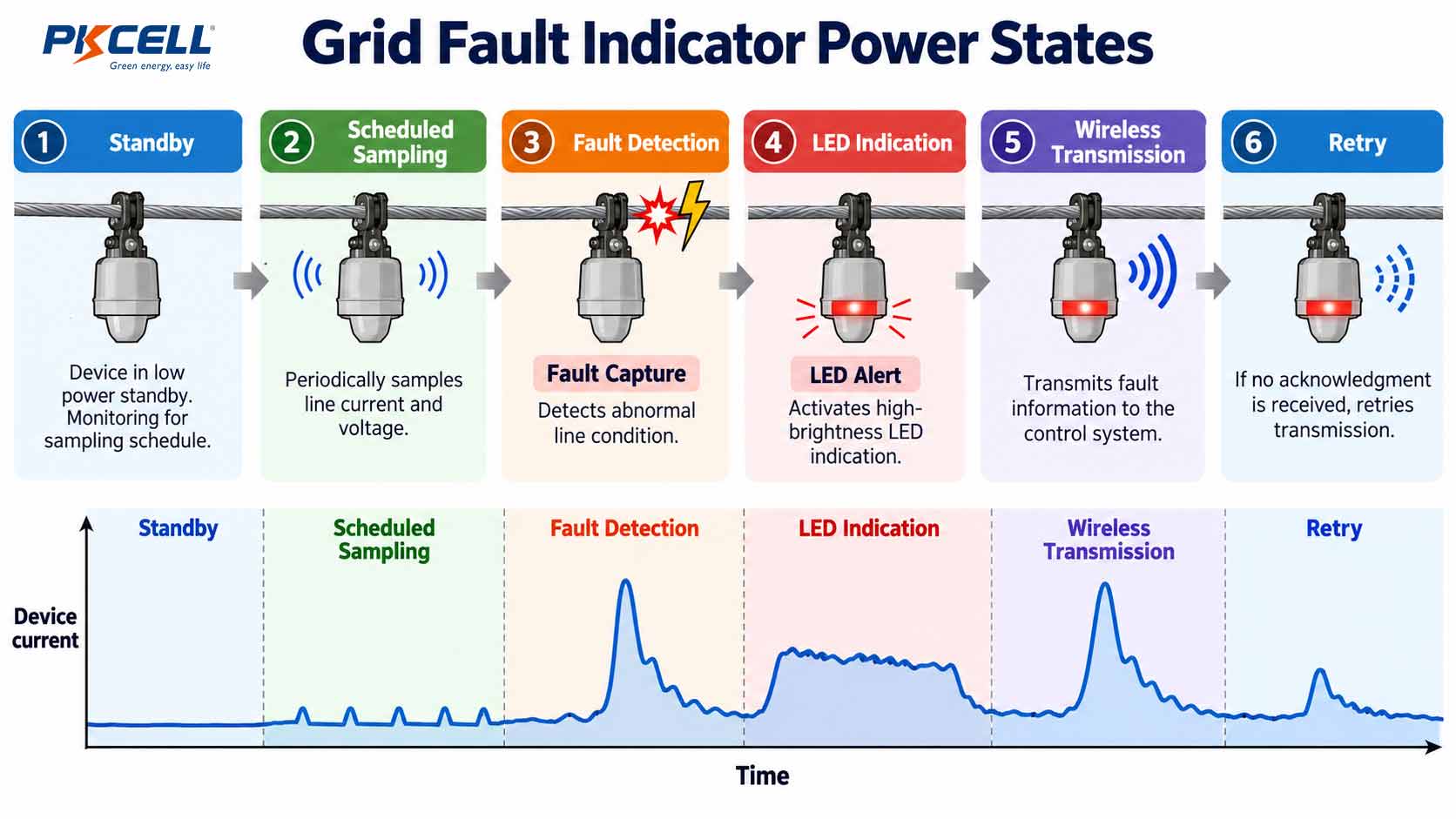
- Sleep or standby: sensing and timing circuits remain active at very low current.
- Scheduled monitoring: the processor wakes to sample, calculate and store data.
- Fault detection: the sensor, processor and memory operate together for event capture.
- Local indication: one or more LEDs may flash for minutes or hours.
- Communication: the radio starts, registers with the network and sends event data.
- Retry or recovery: a weak network may trigger additional transmissions and extend the active period.
Eaton, for example, describes lithium-battery-powered delayed-reset indicators for overhead systems, while communicating distribution sensors can combine visual indication, data storage and cellular or Bluetooth radios. This illustrates why the utility fault indicator power supply must be evaluated against the actual device state machine rather than a single average current value.
Standby Current vs. Fault-Event Current
The standby current usually determines how much energy is consumed over the deployment period. The fault event, however, determines whether the system can operate when it matters most. Both energy and power must therefore be checked independently.
Build a State-Based Energy Budget
Begin with measured current, voltage and duration for every operating state. Include routine health reports, diagnostic wake-ups, LED duty cycles, scheduled transmissions, firmware checks and anticipated fault events. Do not use radio-module headline current alone; measure the complete device at the battery terminals.
Next, add allowance for self-discharge, temperature-related capacity reduction, manufacturing variation, aging and communication retries. The resulting figure is a planning estimate, not a substitute for battery testing in the finished product.
Why Average Current Is Not Enough
A radio transmission may consume little total capacity yet still cause a damaging voltage dip. Battery impedance, cell construction, passivation, temperature, wiring resistance and pulse duration all influence the voltage available to the load.
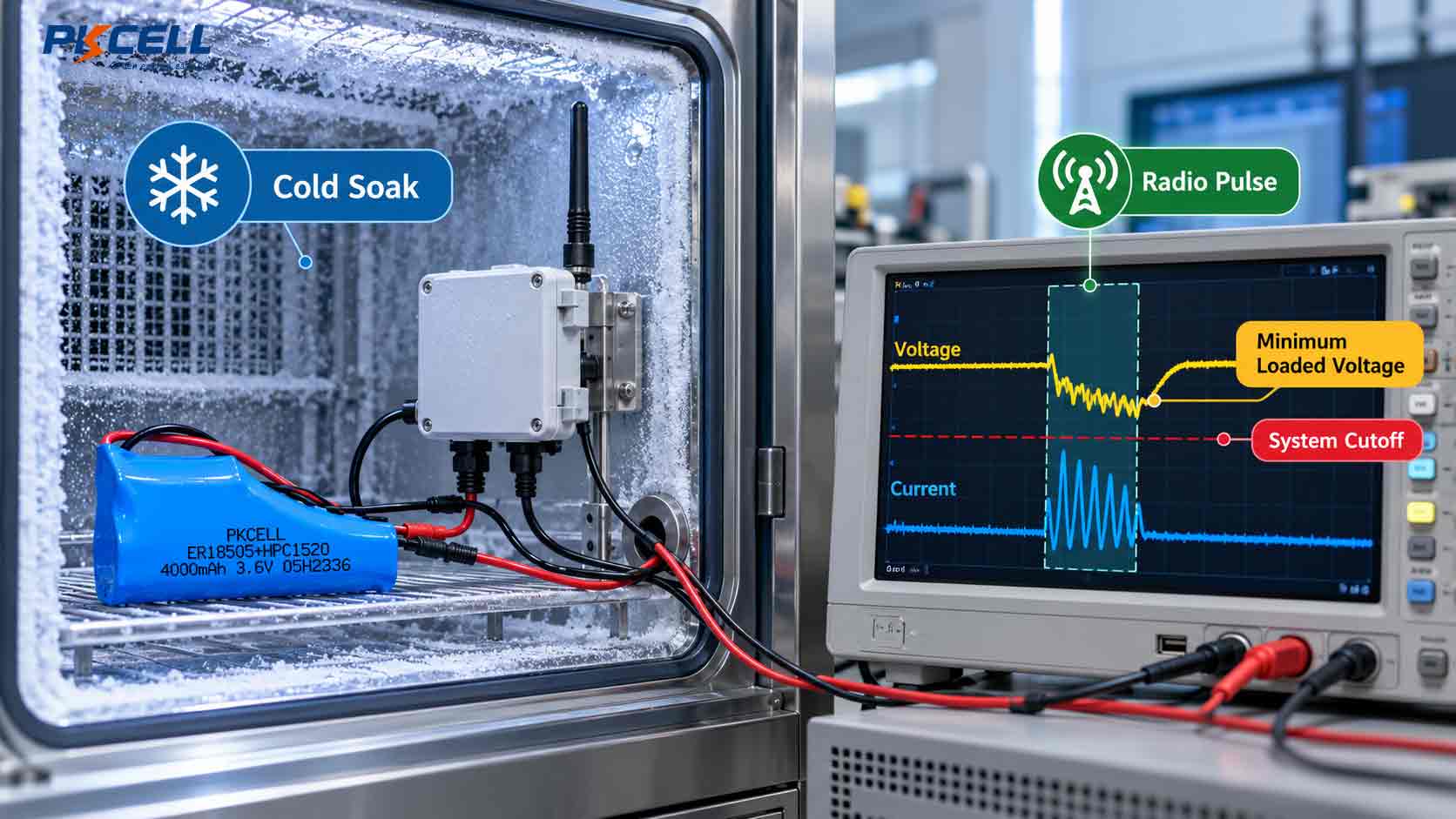
This simple relationship is useful for early screening, but real Li-SOCl₂ pulse behavior is dynamic. Saft notes that the passivation layer naturally formed on the lithium anode can contribute to a temporary voltage drop during a high-current pulse. If voltage falls below the system cutoff, the radio or processor may reset even though the battery still contains substantial energy.
A battery can pass a capacity calculation and still fail the first cold-start transmission. Validate minimum loaded voltage, not only nominal amp-hours.
Model the Worst Event Sequence
Test the full event chain rather than one isolated pulse: wake the processor, acquire the waveform, write memory, flash the indicator, start the radio and execute the expected retry sequence. For a distribution grid monitoring battery, these activities may overlap and create a higher or longer peak than any individual subsystem suggests.
Battery Requirements for Outdoor Temperature and Long Service Intervals
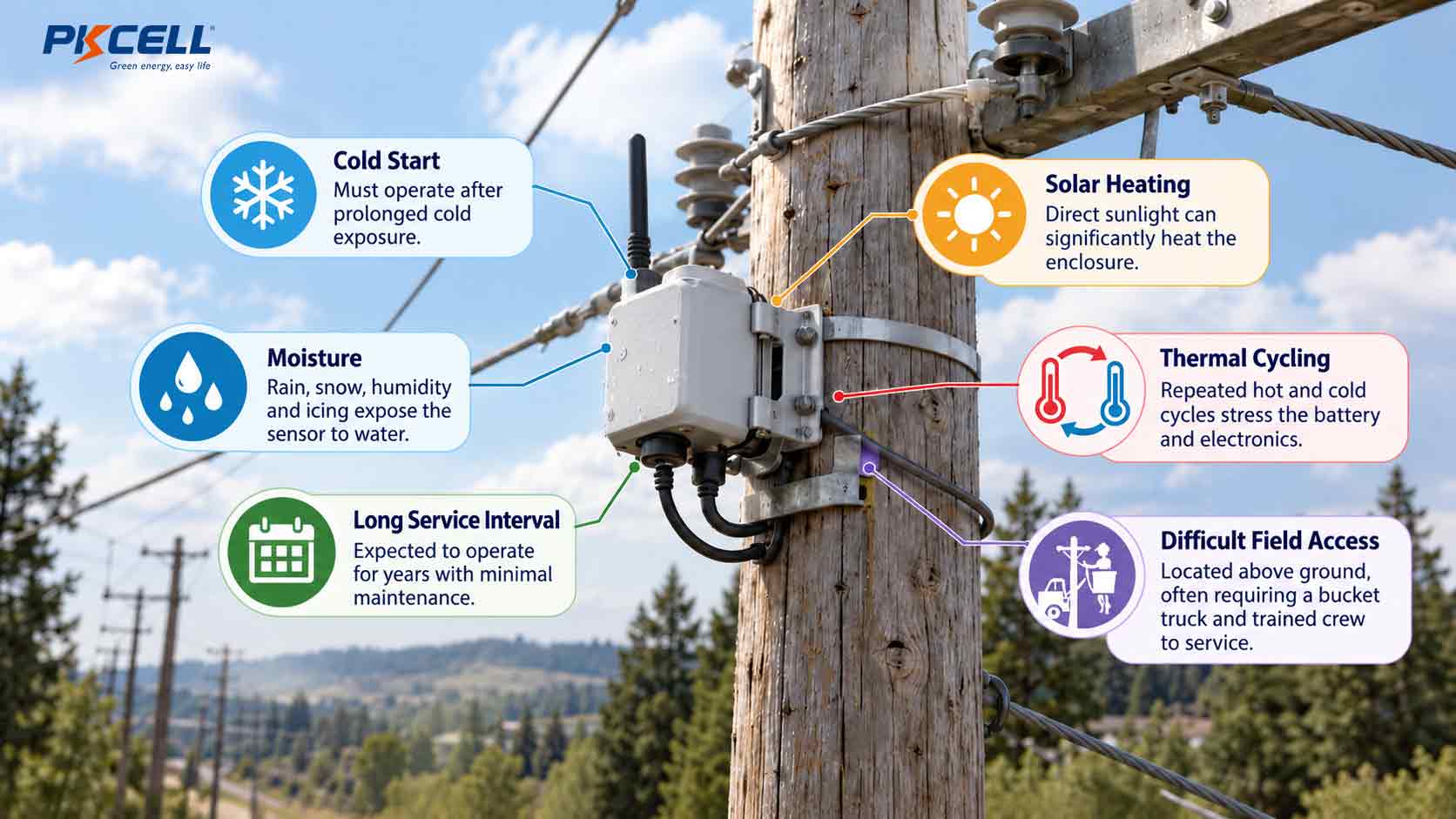
A pole-mounted sensor battery may face cold starts, solar heating, daily thermal cycling, moisture exposure and long periods without maintenance. The cell’s published operating-temperature range is only the beginning of the evaluation.
Check Cold-Pulse Voltage
Low temperature generally reduces electrochemical reaction rate and increases effective impedance. The critical question is whether the battery remains above the device’s minimum operating voltage during fault processing and communication at the coldest specified condition. Test with aged batteries as well as fresh samples.
Account for Heat and Storage History
High temperature can accelerate aging and influence passivation behavior. Include transportation, warehouse storage, enclosure heating and sun exposure in the temperature profile. The battery may experience a more severe temperature inside a sealed enclosure than the reported ambient temperature.
Align Battery Life with the Field Maintenance Cycle
A calculated ten-year runtime does not automatically justify a ten-year service interval. Replacement planning should reflect inspection frequency, access cost, event frequency, radio coverage, enclosure life and the consequence of a missed indication.
- Define a conservative end-of-life voltage under load.
- Reserve energy for fault indication and emergency transmissions near end of life.
- Include network retries and periods of degraded coverage.
- Consider battery replacement during an existing utility inspection cycle.
- Confirm transport, storage and traceability requirements before production release.
Selecting Battery Chemistry and Pack Configuration
The right pole-mounted sensor battery depends on the balance between long-term energy, pulse power, voltage, enclosure space and fault-reporting behavior. No chemistry or configuration should be selected from capacity alone.
| Battery direction | Where it can fit | Engineering checks |
|---|---|---|
| Bobbin-type Li-SOCl₂ cell | Very low standby current, infrequent events and moderate pulse demand | Passivation, cold-pulse voltage, radio cutoff and maximum pulse rating |
| Spiral-type Li-SOCl₂ cell | Applications requiring greater power capability from the cell | Available capacity, self-discharge, pulse duration, temperature and enclosure fit |
| Li-SOCl₂ with HPC or pulse helper | Long standby combined with demanding wireless or LED pulses | Capacitor sizing, recharge interval, leakage, peak voltage and event repetition |
| Custom series or parallel pack | Special voltage, capacity, connector, housing or mechanical requirements | Cell matching, protection, isolation, fault behavior and assembly consistency |
When Li-SOCl₂ Is a Strong Starting Point
Li-SOCl₂ chemistry is often considered for long-life industrial sensors because of its high energy density, low self-discharge and broad model-specific operating-temperature capability. PKCELL offers Li-SOCl₂ battery models in energy-oriented and power-oriented constructions.
Chemistry alone does not guarantee a successful grid sensor design. Engineers must compare the cell’s pulse performance with the radio profile, cutoff voltage, temperature and time spent in storage. A relevant PKCELL electrical distribution case used a 3.6 V ER17505 Li-SOCl₂ cell for long-term standby, monitoring and control functions in a gas circuit breaker. The ER17505 circuit breaker case study demonstrates the importance of matching voltage, current consumption, temperature and expected service life.
When to Add a Hybrid Pulse Capacitor
When radio start-up or repeated fault reporting exceeds the practical pulse capability of an energy-oriented cell, an ER+HPC configuration can separate the design roles: the Li-SOCl₂ cell supplies long-term energy while the pulse helper supports short, high-current demands. Explore PKCELL’s hybrid pulse capacitor battery solutions for long-standby devices with intermittent communication.
The pulse helper must be sized for the required current, pulse width, repeated transmissions and recovery time between events. Its leakage current also belongs in the lifetime budget.
Series and Parallel Pack Decisions
- Series cells increase pack voltage but require confirmation that the maximum fresh-pack voltage is acceptable to the electronics.
- Parallel cells can increase capacity and current capability, but the pack must be engineered with appropriate cell matching and isolation.
- Wires and connectors add resistance and must tolerate outdoor vibration, installation stress and the specified pulse current.
- Protection and encapsulation should suit the electrical architecture and environmental enclosure without introducing excessive standby loss.
OEMs needing a project-specific voltage, capacity, connector, housing or ER+HPC architecture can review PKCELL’s customized primary lithium battery pack service.
How to Validate Runtime and Communication Performance
Validation should reproduce the application, not merely confirm a cell datasheet value. Use production-intent electronics, firmware, connectors and enclosure components wherever possible.
- Record the real load profile. Measure sleep current, sensor sampling, processor activity, LED indication, memory writes, radio registration, payload transmission and retries at the battery terminals.
- Define the voltage limits. Document the cutoff and reset thresholds for the processor, sensor, memory and radio. The highest subsystem requirement may control the battery decision.
- Test temperature corners. Soak the complete device at specified hot and cold conditions long enough to stabilize before triggering a representative event.
- Include storage and passivation scenarios. Test a transmission after an extended dormant period, especially when using Li-SOCl₂ cells.
- Simulate weak network coverage. Force registration delays, retransmissions and the longest credible communication window.
- Evaluate aged batteries. Repeat the worst event with batteries representing the intended end-of-life condition, not only fresh cells.
- Run repeated fault events. Confirm that back-to-back events do not exhaust the pulse helper or pull the pack below the system cutoff.
- Verify mechanical integration. Inspect connector retention, cable routing, polarity control, sealing, vibration resistance and service access.
Teams comparing several primary lithium directions can also use PKCELL’s Primary Lithium Battery Solution Hub to review chemistry, pulse-current and custom-pack options before requesting samples.
Common Selection Mistakes
- Choosing a battery from nominal amp-hours without measuring communication pulses.
- Testing only at room temperature with fresh cells.
- Ignoring voltage delay after a long dormant period.
- Assuming every fault creates only one successful transmission.
- Leaving LED indication time out of the energy budget.
- Using the cell’s operating-temperature range as proof of complete-device performance.
- Failing to reserve energy for an end-of-life fault report.
- Adding parallel cells without a properly engineered pack architecture.
- Ignoring connector and cable resistance during peak-load tests.
Frequently Asked Questions
What is the best battery for a grid fault indicator?
There is no universal model. A low-standby indicator with infrequent, moderate pulses may suit a bobbin-type Li-SOCl₂ cell, while a communicating unit with higher radio peaks may require a power-type cell or Li-SOCl₂ plus a pulse helper. Selection must be based on measured current, minimum voltage, temperature and service-life requirements.
Why can a high-capacity battery still reset the radio?
Capacity measures stored energy, not instantaneous power. Battery impedance, low temperature, passivation and connection resistance can cause loaded voltage to fall below the radio or processor cutoff during a short pulse.
Should runtime be calculated from average current?
Average current is useful for an initial energy estimate, but each device state should be calculated separately. Pulse voltage, communication retries, self-discharge, environmental derating and end-of-life reserve must also be evaluated.
When is an ER+HPC battery pack appropriate?
It is worth evaluating when the application combines long standby periods with short, demanding communication or indication pulses. The pulse helper should be validated for peak current, pulse duration, recovery time, leakage and repeated-event behavior.
What should an OEM provide when requesting samples?
Provide the current waveform, operating and cutoff voltages, temperature profile, target service interval, mechanical envelope, connector details, communication technology, retry behavior and estimated annual demand.
Choose for the Fault Event, Not Just the Standby Years
A reliable grid fault indicator battery must satisfy two different objectives: preserve energy through a long unattended deployment and deliver enough voltage and current during the event that justifies the device’s installation. That requires a state-based energy budget, worst-case pulse testing, environmental validation and a maintenance strategy with realistic reserve.
By validating the complete fault-and-communication sequence at temperature and near end of life, manufacturers can reduce field resets, missed reports and premature battery replacement.
Discuss Your Grid Monitoring Battery Requirement
Send PKCELL your voltage range, measured load profile, communication pulse, operating temperature, target service interval, battery compartment dimensions and connector requirements. The engineering team can help evaluate Li-SOCl₂ cells, ER+HPC solutions and custom primary battery packs for your device.
Request a Battery Recommendation
Explore Custom Battery Packs
Post time: Oct-20-2026


